A large racetrack-shaped shaft forging die

A racetrack-shaped and mold technology, applied in manufacturing tools, engine components, forging/pressing/hammer devices, etc., can solve the problems of lack of market competitiveness, influence on strength, low efficiency, etc., to improve the effect of alignment and shaping, improve The accuracy of shaft parts and the effect of improving the reclaiming speed

Active Publication Date: 2021-06-15
威海区域创新中心有限责任公司
View PDF6 Cites 0 Cited by
  • Summary
  • Abstract
  • Description
  • Claims
  • Application Information

AI Technical Summary

Problems solved by technology

However, the precision of ordinary cold-forged shafts is not enough, and alignment shaping is required, which is inefficient, error-prone, and unstable in quality. The traditional processing method of this part is machining a large racetrack-shaped shaft, which makes the processing difficult and slow. , destroy the fiber orientation of the part, and affect the strength; in addition, there are also shortcomings such as low material utilization, high overall cost, and lack of market competitiveness.

Method used


Image

  • A large racetrack-shaped shaft forging die
  • A large racetrack-shaped shaft forging die
  • A large racetrack-shaped shaft forging die

Examples


Embodiment 1

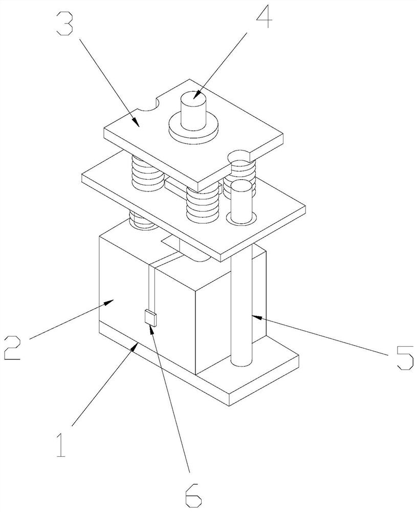
[0028] see Figure 1-Figure 5 , the present invention provides a large racetrack-shaped shaft forging die, the structure of which includes a die base 1, a forging die 2, a balance power mechanism 3, a stamping mechanism 4, a fixed rod 5, and a stripping mechanism 6. The bottom of the forging die 2 There is a die base 1 under the end, the forging die 2 is connected with the die base 1, a balance power mechanism 3 is arranged on the top of the forging die 2, and the forging die 2 and the balance power mechanism 3 pass through the fixed rod 5 Sliding fit, the top of the balance power mechanism 3 is provided with a stamping mechanism 4, the balance power mechanism 3 and the stamping mechanism 4 are mechanically connected, and a stripping mechanism 6 is installed inside the forging die 2.

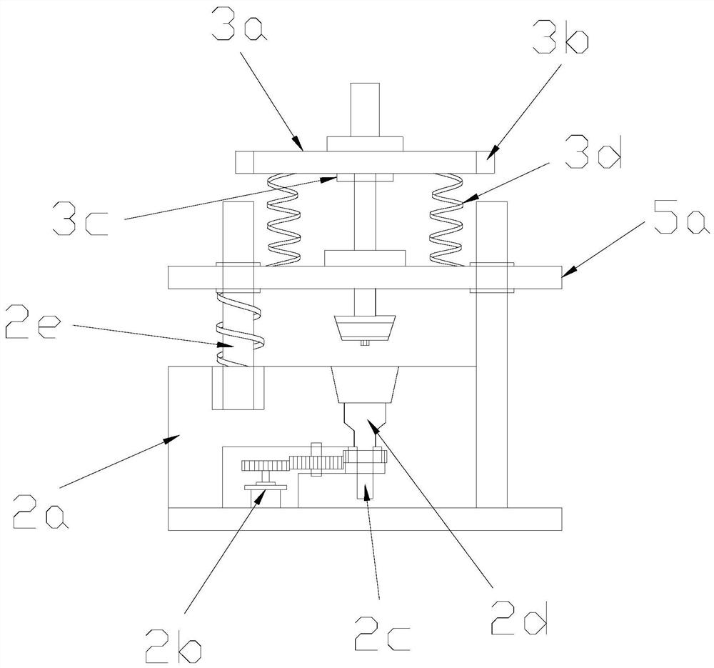
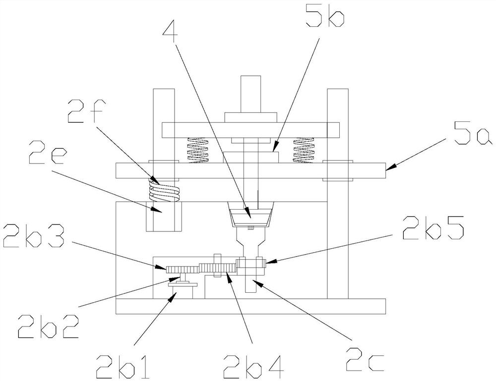
[0029] The forging die 2 is composed of a die body 2a, a rotating mechanism 2b, a shaft length adjustment column 2c, a shaft mold groove 2d, a support column 2e, and a first spring 2f, and a rot...

Embodiment 2

[0036] see Figure 1-Figure 6 , the present invention provides a large racetrack-shaped shaft forging die, the balance power mechanism 3 is composed of a sliding plate 3a, a chute 3b, a gasket 3c, and a second spring 3d, and the left and right ends of the sliding plate 3a are Both are provided with a chute 3b, a spacer 3c is provided under the middle position of the bottom end of the sliding plate 3a, the sliding plate 3a and the spacer 3c are fixedly connected, and two bottom ends of the sliding plate 3a are installed For the second spring 3d, a support plate 5a is provided on the surface of the fixed rod 5, and the fixed rod 5 and the support plate 5a are slidingly fitted.

[0037] Described stripping mechanism 6 is made up of lifting slide block 6a, model block 6b, magnet sheet 6c, and described model block 6b left end is provided with lift slide block 6a, and described model block 6b and lift slide block 6a is an integrated structure, the right side of the model block 6b ...


PUM


Abstract

The invention discloses a large racetrack-shaped shaft forging die. Its structure includes a die seat, a forging die, a balance power mechanism, a stamping mechanism, a fixing rod and a stripping mechanism. The accuracy of the shaft parts is improved, and the forging blank is clamped and rotated by driving the fitting convex ring through the rotating mechanism, which improves the alignment and shaping effect of the forging blank during forging. It is formed once, and the density of the shaft is solidified during the forming process. The buffer head is used to reduce the anti-vibration force when pressing the forging blank, avoid the damage to the mechanical power source caused by the anti-vibration force, and improve the use of the machine. The forging die uses the balanced power mechanism to provide a stable and accurate sliding trajectory for the power rod during stamping and forging, so as to avoid the damage of the shaft due to deviation during stamping. The forging die needs to be disassembled again.

Description

technical field [0001] The invention relates to the field of dies, in particular to a large racetrack-shaped shaft forging die. Background technique [0002] A forging die is a tool that can shape a blank into a die forging. The forging die is the necessary key process equipment in the production of die forgings. It is a tool that needs to be used in every stroke of the equipment, and plays a pivotal role in the production of die forgings. However, the precision of ordinary cold-forged shafts is not enough, and alignment shaping is required, which is inefficient, error-prone, and unstable in quality. The traditional processing method of this part is machining a large racetrack-shaped shaft, which makes processing difficult and slow. 1. Destroy the fiber orientation of the parts and affect the strength; in addition, there are also shortcomings such as low material utilization, high overall cost, and lack of market competitiveness. Contents of the invention [0003] Aiming...

Claims


Application Information

Patent Timeline
Patent Type & Authority Patents(China)
IPC IPC(8): B21J13/02B21J13/08B21K1/06
CPCB21J13/02B21J13/08B21K1/06
Inventor 陈植炜张巧
Owner 威海区域创新中心有限责任公司
Why Eureka
Try Eureka