


Quick Research
Generate reliable direction feasibility study reports for your R&D in just a few steps.

Technical Q&A
Discover and master advanced knowledge NOW. Basics, ideas, possibilities, all at once.

Find Solutions
As an expert in R&D theories, this can generate solutions to your technical problems instantly.

Evaluate Feasibility
Analyze your overall solution with one click, know your potential R&D risks in advance.

Monitor Landscape
Get weekly tech updates, stay abreast of the latest tech innovations and key insights.
Special-shaped sealed heat dissipation and conduction device
A conduction device and special-shaped sealing technology, which can be used in decoration, cooling/ventilation/heating transformation, electrical components, etc. through conduction and heat transfer. Problems such as increased difficulty, increased noise and energy consumption of electronic equipment, etc., achieve the effect of simple dustproof and waterproof, simple structure, and reduced air resistance
- Summary
- Abstract
- Description
- Claims
- Application Information
AI Technical Summary
Problems solved by technology
Method used
Image

Examples
Embodiment 1
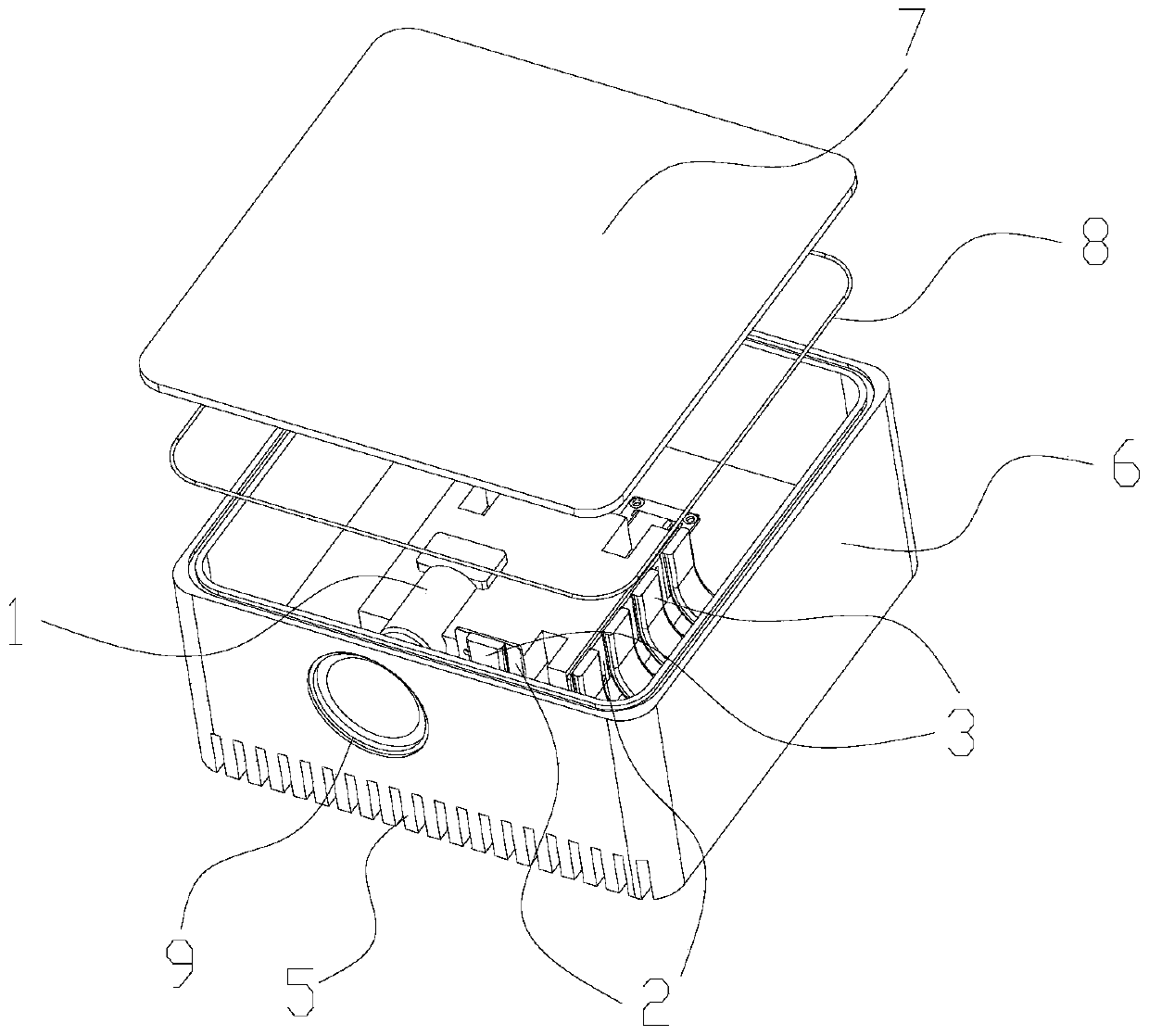
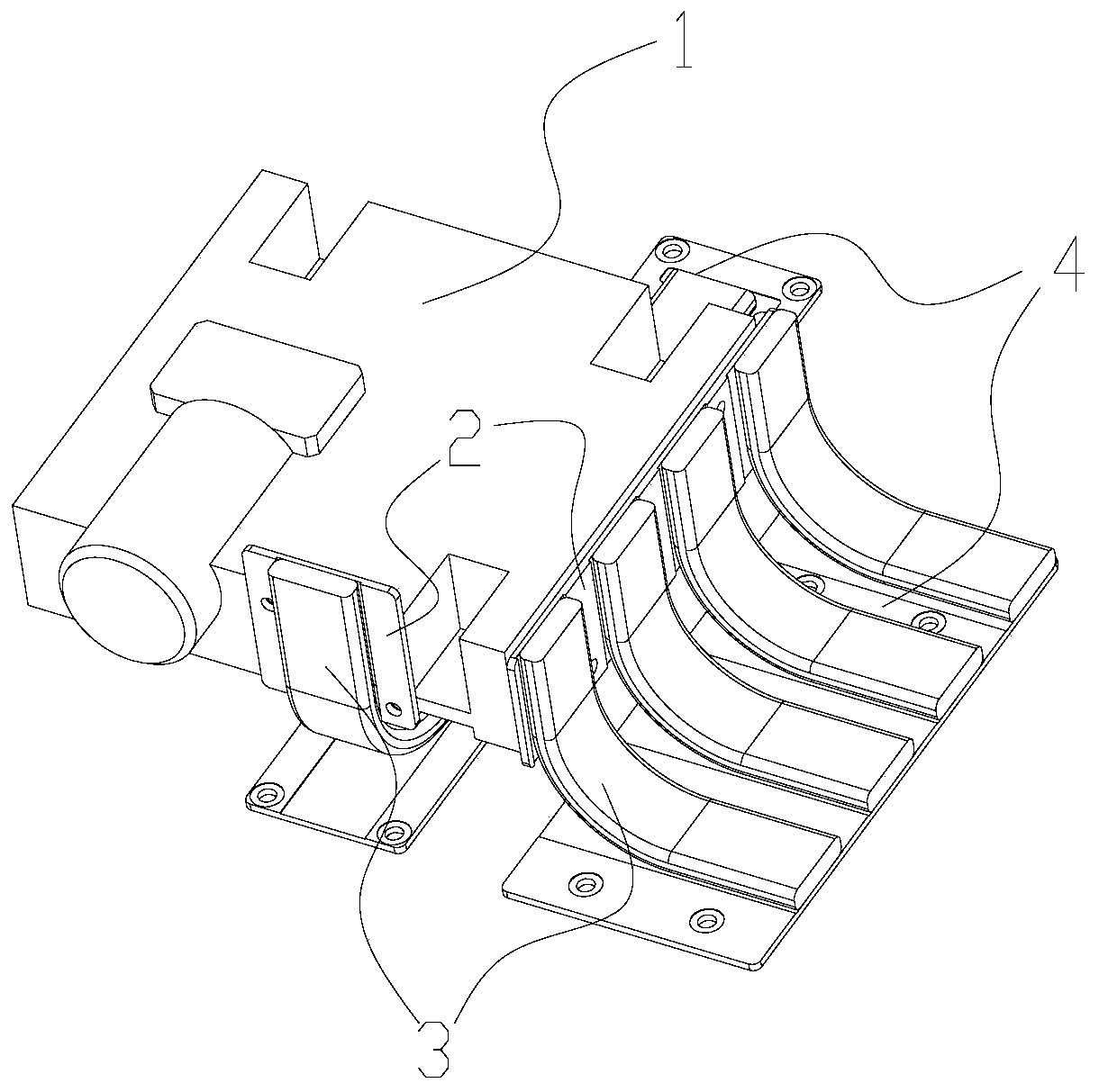
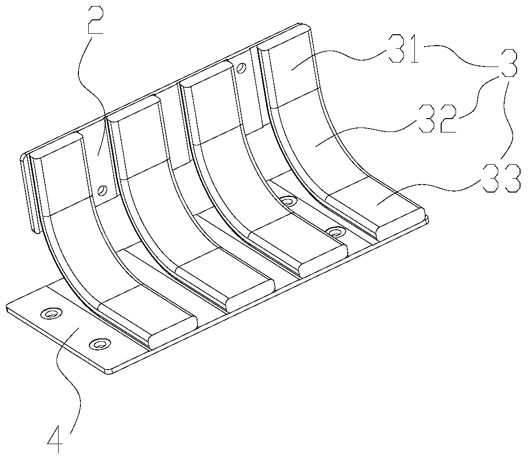
[0027] Such as Figure 1-4 As shown, this embodiment provides a special-shaped sealed heat dissipation conduction device, including a heat dissipation element 1, a heat dissipation assembly, and a sealing box. Both the heat dissipation element 1 and the heat dissipation assembly are arranged inside the sealing box, and the waterproof and dustproof of the heat dissipation assembly is enhanced through the sealing box. effect, so as to ensure its IP level, the heat dissipation assembly includes the first heat dissipation copper plate 2, the heat pipe 3, the second heat dissipation copper plate 4, the heat dissipation end of the heat dissipation element 1 is connected with one end of the first heat dissipation copper plate 2, and the other end of the first heat dissipation copper plate 2 One end is connected to one end of the heat pipe 3, and the other end of the heat pipe 3 is connected to one end of the second heat dissipation copper plate 4; the sealed box is provided with heat ...
Embodiment 2
[0030] Such as Figure 1-4As shown, this embodiment provides a special-shaped sealed heat dissipation conduction device, including a heat dissipation element 1, a heat dissipation assembly, and a sealing box. Both the heat dissipation element 1 and the heat dissipation assembly are arranged inside the sealing box, and the waterproof and dustproof of the heat dissipation assembly is enhanced through the sealing box. effect, so as to ensure its IP level, the heat dissipation assembly includes the first heat dissipation copper plate 2, the heat pipe 3, the second heat dissipation copper plate 4, the heat dissipation end of the heat dissipation element 1 is connected with one end of the first heat dissipation copper plate 2, and the other end of the first heat dissipation copper plate 2 One end is connected to one end of the heat pipe 3, and the other end of the heat pipe 3 is connected to one end of the second heat dissipation copper plate 4; the sealed box is provided with heat d...
Embodiment 3
[0034] This embodiment is a further improvement made on the basis of Embodiment 1 or Embodiment 2. The specific differences between this embodiment and Embodiment 1 or Embodiment 2 are:
[0035] What needs to be further explained in this embodiment is that the sealed box includes a product shell 6 with an open upper end and an upper cover 7 installed at the open end of the product shell 6, and a box sealing ring 8 is installed between the product shell 6 and the upper cover 7 , the cooling fins 5 are arranged at one end of the product housing 6 . The sealing box sealed by the box sealing ring 8, as the sealing structure of the present invention, can well protect the heat dissipation element, achieve better dustproof and waterproof effects, and can make the heat dissipation element reach a higher IP level.
PUM
 Abstract
Description
Claims
Application Information
 - R&D Engineer
- R&D Manager
- IP Professional
- Industry Leading Data Capabilities
- Powerful AI technology
- Patent DNA Extraction
Browse by: Latest US Patents, China's latest patents, Technical Efficacy Thesaurus, Application Domain, Technology Topic, Popular Technical Reports.
© 2024 PatSnap. All rights reserved.Legal|Privacy policy|Modern Slavery Act Transparency Statement|Sitemap|About US| Contact US: help@patsnap.com