
Satellite array antenna based on mirror image subarrays

An array antenna and sub-array technology, applied in the field of satellite array antennas, can solve the problems of low radiation efficiency, difficult installation, and large size of the antenna, and achieve the effects of compact array antenna structure, low cross-polarization, and high radiation efficiency

Active Publication Date: 2020-06-02
ZHEJIANG UNIV
View PDF11 Cites 4 Cited by
  • Summary
  • Abstract
  • Description
  • Claims
  • Application Information

AI Technical Summary

Problems solved by technology

Although the traditional reflector antenna has a simple structure and is easy to achieve high gain, it is bulky and difficult to install. Therefore, planar array antennas with small size, high efficiency, and easy integration have been widely used
In order to achieve high Q value and low loss in the dual-polarized planar array antenna, it is necessary to choose a waveguide-based planar array antenna, because although the microstrip patch planar array antenna is easy to integrate with the RF backend, its antenna radiation efficiency is low, and the unit The mutual coupling between the antennas is relatively strong. As the design operating frequency of the antenna increases, the overall radiation performance of the antenna will deteriorate more and more.
However, the feed network of the dual-polarized waveguide array antenna takes up a lot of space and is heavy, so it is difficult for the traditional antenna structure to meet the technical requirements of small size, low sidelobe, and low loss at the same time.

Method used


Image

  • Satellite array antenna based on mirror image subarrays
  • Satellite array antenna based on mirror image subarrays
  • Satellite array antenna based on mirror image subarrays

Examples


Embodiment

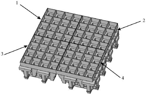
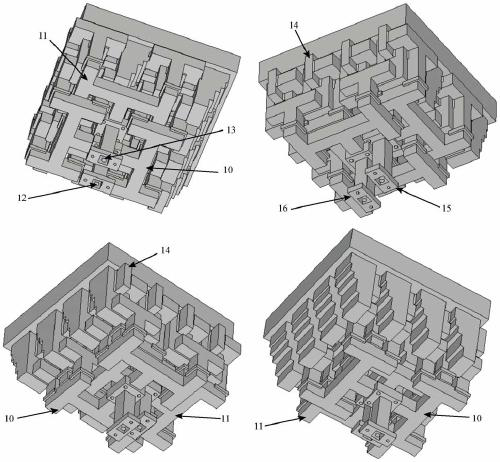
[0038] figure 1 The structure of the satellite array antenna used in this embodiment is shown, and the satellite array antenna is composed of 8×8 64 radiation units. The array antenna is composed of four sub-arrays (1, 2, 3, 4), each sub-array has an independent feed network, and the sub-arrays (1, 2), (3, 4) along the horizontal polarization direction are mirror-symmetrical, The feeding network and the radiating unit are mirror symmetrical at the same time.

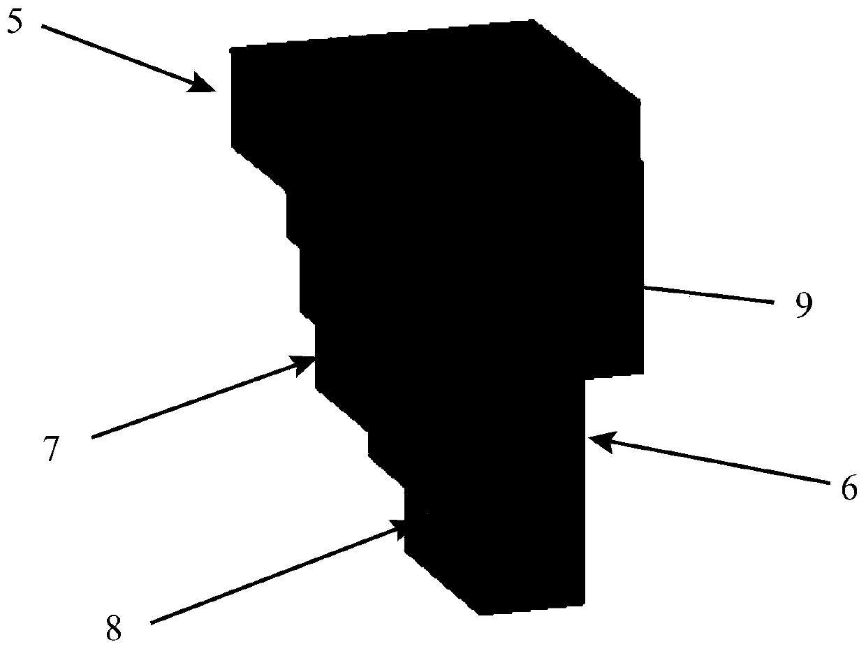
[0039] figure 2 The structure of the radiation unit is shown, mainly composed of a radiation outer cavity (5) and a radiation inner cavity (6). The radiation outer cavity is the position where the radiation unit radiates electromagnetic waves outward, and its aperture is larger than that of the radiation inner cavity to achieve higher gain and radiation efficiency. One side of the radiation inner cavity is designed as a stepped surface structure (7), so that the radiation unit can achieve good radiation performance i...


PUM


Abstract

The invention discloses a satellite array antenna based on mirror image subarrays. The antenna is of polarization form of dual-linear polarization and works in a Ku frequency band. The antenna is mainly formed by tightly arranging four small sub-arrays of an all-copper structure in a 2*2 rectangular array mode, the adjacent subarrays in one direction of the rectangular array are in mirror symmetry, and the adjacent subarrays in the other perpendicular direction of the rectangular array are the same in arrangement and are in translation replication relation with one another. According to the invention, the dual-linear polarization satellite array antenna based on the square coaxial structure and the mirror image subarrays is designed under the condition of a high Q value; and a tightly nested feed network structure integrated with the satellite array antenna radiation unit can solve the technical problems of difficulty in integration, large size, high loss and the like of the existing horn-type communication-in-motion satellite array antenna structure adopting waveguide or coaxial feed. The satellite array antenna realizes very low cross polarization under the condition that the antenna structure only needs one-time phase inversion.

Description

technical field [0001] The invention designs a satellite array antenna based on mirrored sub-arrays, which has the characteristics of high gain, dual polarization, low side lobe, small size, low cross polarization and the like. Background technique [0002] One of the key technologies in satellite communication systems is antenna technology. Satellite communication antennas often require antennas with high efficiency, low loss, dual-linear polarization, and circular polarization. The mobile communication antenna technology especially requires the antenna to have the characteristics of small size. Although the traditional reflector antenna has a simple structure and is easy to achieve high gain, it is bulky and difficult to install. Therefore, planar array antennas with small size, high efficiency, and easy integration have been widely used. In order to achieve high Q value and low loss in the dual-polarized planar array antenna, it is necessary to choose a waveguide-based p...

Claims


Application Information

Patent Timeline
Patent Type & Authority Applications(China)
IPC IPC(8): H01Q1/36H01Q1/50H01Q21/00
CPCH01Q1/36H01Q1/50H01Q21/00
Inventor 王浩冉立新
Owner ZHEJIANG UNIV
Learn More