
Bean type battery and manufacturing method thereof

A battery and cell technology, which is applied in the field of bean-type batteries and its production, can solve the problems of space occupation, high production cost, and poor battery sealing, so as to increase space utilization, ensure that the seal does not fail, and have good thickness consistency Effect

Inactive Publication Date: 2020-05-29
EVE ENERGY CO LTD
View PDF4 Cites 2 Cited by
  • Summary
  • Abstract
  • Description
  • Claims
  • Application Information

AI Technical Summary

Problems solved by technology

The bean-type battery prepared in this way has the following defects: 1. The upper end of the sealing ring is generally provided with a hook structure to hang on the top of the bottom case. 2. The sealing ring part is located on the inner wall of the bottom case, which occupies the space inside the bottom case, reducing the space utilization rate and the energy density of the battery; 3. The size of the bean-type battery is small, so it is sealed The thickness of the ring needs to be very thin, which increases the difficulty of making the sealing ring. At the same time, it is difficult to ensure the consistency of the thickness and size of the thin sealing ring, so the assembled battery is poor in sealing
[0003] In addition, the tabs of the wound-type cells of the current conventional bean-type batteries are all located at the ends of the pole pieces, which makes the current bean-type batteries have shortcomings in fast charging and high-rate discharge performance.

Method used


Image

  • Bean type battery and manufacturing method thereof
  • Bean type battery and manufacturing method thereof
  • Bean type battery and manufacturing method thereof

Examples


Embodiment Construction

[0054] In order to make the technical problems solved by the present invention, the technical solutions adopted and the technical effects achieved clearer, the technical solutions of the embodiments of the present invention will be further described in detail below in conjunction with the accompanying drawings. Obviously, the described embodiments are only the technical solutions of the present invention. Some, but not all, embodiments. Based on the embodiments of the present invention, all other embodiments obtained by those skilled in the art without creative efforts fall within the protection scope of the present invention.

[0055] In the description of the present invention, unless otherwise clearly specified and limited, the terms "connected", "connected" and "fixed" should be understood in a broad sense, for example, it can be a fixed connection, a detachable connection, or an integrated ; It can be a mechanical connection or an electrical connection; it can be a direct...


PUM

PropertyMeasurementUnit
diameteraaaaaaaaaa
thicknessaaaaaaaaaa
glass transition temperatureaaaaaaaaaa

Abstract

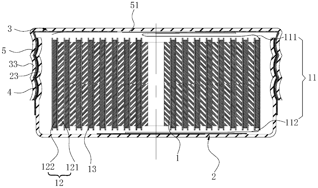
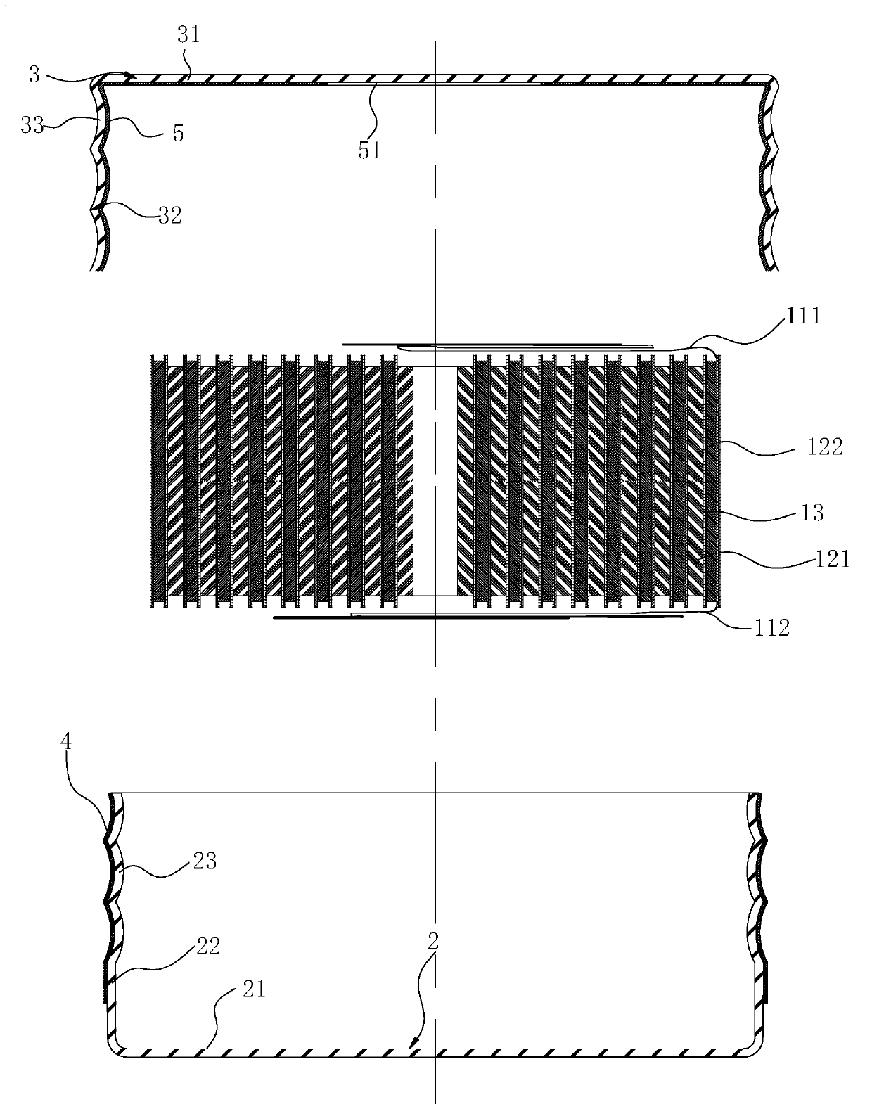
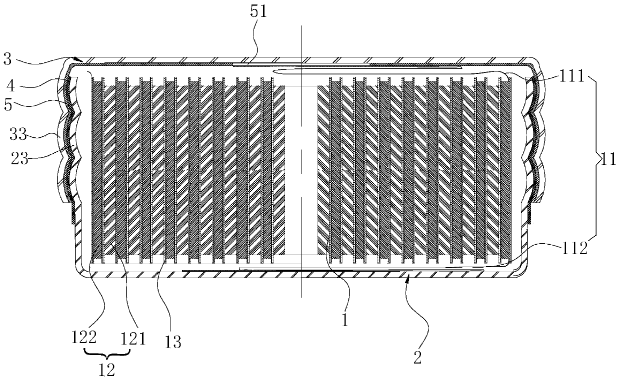
The invention discloses a bean type battery and a manufacturing method thereof. The bean type battery comprises a shell and a winding type battery cell. The shell comprises a bottom shell and a covercap; the bottom shell and the cover cap are both metal pieces; the bottom shell comprises a bottom plate and a first surrounding wall annularly arranged on one side surface of the bottom plate; the cover cap comprises a top plate and a second surrounding wall annularly arranged on one side surface of the top plate; the second surrounding wall sleeves the first surrounding wall; a first arc-shapedpart is arranged on the first surrounding wall; a second arc-shaped part matched with the first arc-shaped part is arranged on the second surrounding wall; a first insulating sealing film is adhered to an outer surface of the first surrounding wall; and a second insulating sealing film is adhered to an inner surface of the second surrounding wall, the first insulating sealing film and the second insulating sealing film abut against each other and then are cured into a whole body so as to form a sealing layer, a pole piece of the winding type battery cell is strip-shaped, and a tab is arrangedin a center of a length direction or at least two tabs are arranged on the pole piece. The bean type battery is simple in structure, good in sealing effect, high in space utilization rate and energy density and capable of achieving quick charging and high-rate discharging.

Description

technical field [0001] The invention relates to the technical field of batteries, in particular to a bean-type battery and a manufacturing method thereof. Background technique [0002] A bean battery is a very small battery, also known as a button battery or a button battery. A bean-type battery generally includes a bottom case, a cap, and a battery cell disposed in the cavity formed by the two. Since the size of the bean-type battery is very small, it is very difficult to seal it. The conventional assembly process of the bean-type battery is as follows: set the sealing ring on the bottom case, place the battery and other operations, and then set the cap on the bottom case for sealing. The bean-type battery prepared in this way has the following defects: 1. The upper end of the sealing ring is generally provided with a hook structure to hang on the top of the bottom case. 2. The sealing ring part is located on the inner wall of the bottom shell, which occupies the space in...

Claims


Application Information

Patent Timeline
Patent Type & Authority Applications(China)
IPC IPC(8): H01M2/08H01M2/26H01M2/02H01M10/04
CPCH01M10/0427H01M10/0431H01M50/109H01M50/183H01M50/538Y02E60/10Y02P70/50
Inventor 李桂平葛辉明李碧梅李念袁中直祝媛刘金成
Owner EVE ENERGY CO LTD
Learn More