
Patsnap Eureka
For R&D, Patsnap Eureka makes reading and utilizing patents & technical documents easy.
Patsnap Eureka AIR
Designed for self-driven R&D workflows. Generate viable solutions, solve complex R&D challenges, empower your innovation with AI.

Patsnap Eureka Materials
Designed for material experts only. Revolutionize your material R&D, from search, analyze, to developing new materials.

TechResearch
Generate reliable direction feasibility study reports for your R&D in just a few steps.

TechSeek
Discover and master advanced knowledge NOW. Basics, ideas, possibilities, all at once.

TechMind
As an expert in R&D Theories, TechMind can generates customized viable solutions instantly.

TechRisk
Analyze your overall solution with one click, know your potential R&D risks in advance.

TechMonitor
Get weekly tech updates, stay abreast of the latest tech innovations and key insights.
Mold and method for micro part machining
A technology of micro parts and molds, applied in the field of micro forming, can solve the problems that macro molds cannot achieve the required accuracy, it is difficult to meet the accuracy requirements of micro parts, and it is not suitable for micro parts processing, etc., to save processing time, low production efficiency, and general high sex effect
- Summary
- Abstract
- Description
- Claims
- Application Information
AI Technical Summary
Problems solved by technology
Method used
Image

Examples
Embodiment 1
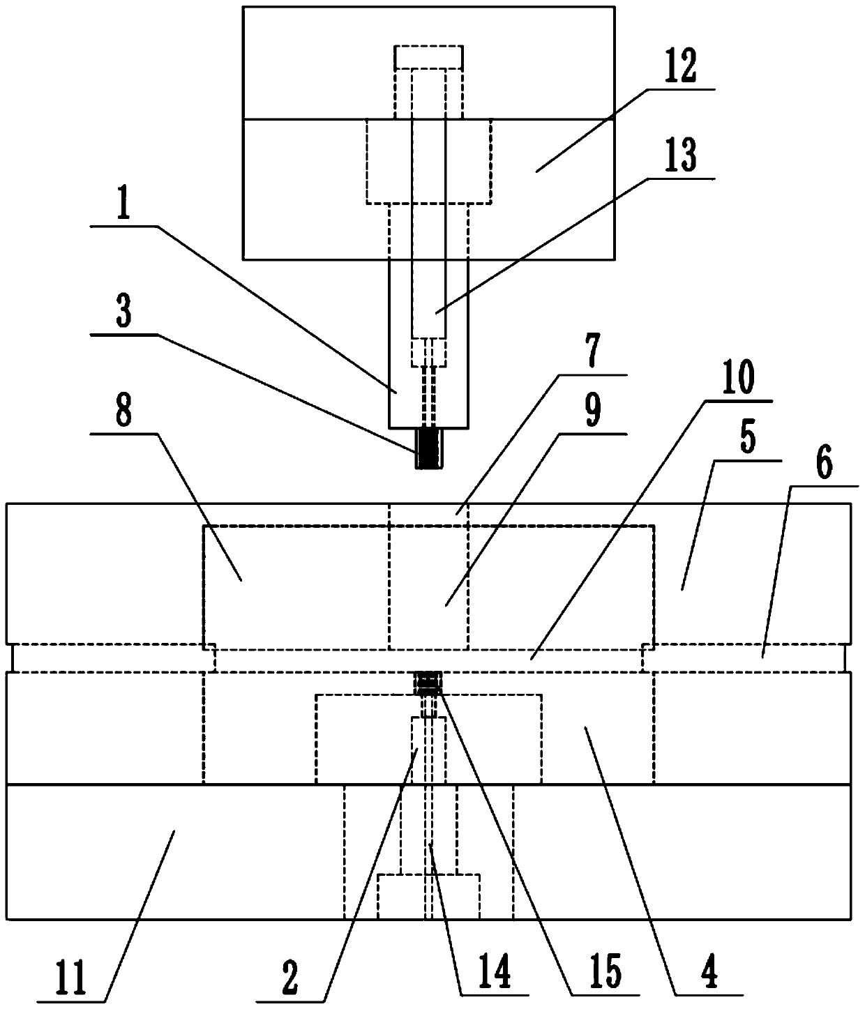
[0042] In a typical implementation of the present application, such as Figure 1-Figure 6As shown, a mold for micro-part processing is proposed.
[0043] The overall structure of the mold is divided into upper and lower parts:
[0044] Among them, the upper mold part is installed on the executive mechanism of the external punching machine, and reciprocates in the vertical direction under the action of the mechanism;
[0045] It includes: an upper punch 1, a through hole punch 13 and a base 12, the base is located at the top of the upper punch, the upper punch is installed on the external punching machine through the base, and the lower end of the upper punch is provided with a workpiece protrusion Die 3, the through-hole punch and the upper punch are arranged coaxially, the upper punch is located outside the through-hole punch, and the through-hole punch reciprocates axially along the upper tap under the action of external force;
[0046] Of course, it can be understood that...
Embodiment 2
[0064] In another typical embodiment of the present application, such as Figure 5 As shown, a kind of micro-part-oriented processing method is provided, utilizing the mold for micro-part processing described in Embodiment 1, the specific steps are as follows:
[0065] Insert the through-hole punch into the upper punch, then install the upper punch on the actuator of the punching machine through the base, fix the flange lower die on the base, and set the lower die on the outside of the flange lower die, So that the bottom surface is in contact with the base, installed on the workbench of the punching machine, the die on the lower die is facing the punch at the bottom of the upper punch;
[0066] Place the blank support stably on the lower die, the bottom of the blank support touches the top surface of the base, closely fit to form a stable support, and form a support hole structure, set the support cover outside the blank support, so that the feed hole and the support hole are...
PUM
 Abstract
Description
Claims
Application Information
 - R&D Engineer
- R&D Manager
- IP Professional
- Industry Leading Data Capabilities
- Powerful AI technology
- Patent DNA Extraction
Browse by: Latest US Patents, China's latest patents, Technical Efficacy Thesaurus, Application Domain, Technology Topic, Popular Technical Reports.
© 2024 PatSnap. All rights reserved.Legal|Privacy policy|Modern Slavery Act Transparency Statement|Sitemap|About US| Contact US: help@patsnap.com