Arc extinguishing chamber pressure measuring device and pressure guide pipe thereof

A technology of measuring device and interrupter, which is applied in the direction of measuring device, measuring fluid pressure, circuit breaker testing, etc. It can solve the problems of vibration induced by air duct, pressure pulse generation, rapid pressure rise, etc., so as to suppress vibration and improve Damping effect, the effect of reducing the influence of measurement results

Inactive Publication Date: 2020-05-26
PINGGAO GRP +1
View PDF6 Cites 0 Cited by
  • Summary
  • Abstract
  • Description
  • Claims
  • Application Information

AI Technical Summary

Problems solved by technology

[0005] The purpose of the present invention is to provide a pressure guiding conduit to solve the problem that in the prior art, during the breaking process of the circuit breaker, the pressure in the arc extinguishing chamber will rise rapidly, resulting in a pressure pulse, which will cause pressure in the existing air guide tube The technical problem of inciting oscillations; the purpose of the present invention is to provide a pressure measurement device for the arc extinguishing chamber to solve the problem that the pressure in the arc extinguishing chamber will rise rapidly during the breaking process of the circuit breaker in the prior art, resulting in pressure pulses. technical problem with this pulse causing oscillations in the existing airway

Method used


Image

  • Arc extinguishing chamber pressure measuring device and pressure guide pipe thereof
  • Arc extinguishing chamber pressure measuring device and pressure guide pipe thereof
  • Arc extinguishing chamber pressure measuring device and pressure guide pipe thereof

Examples


Embodiment 1

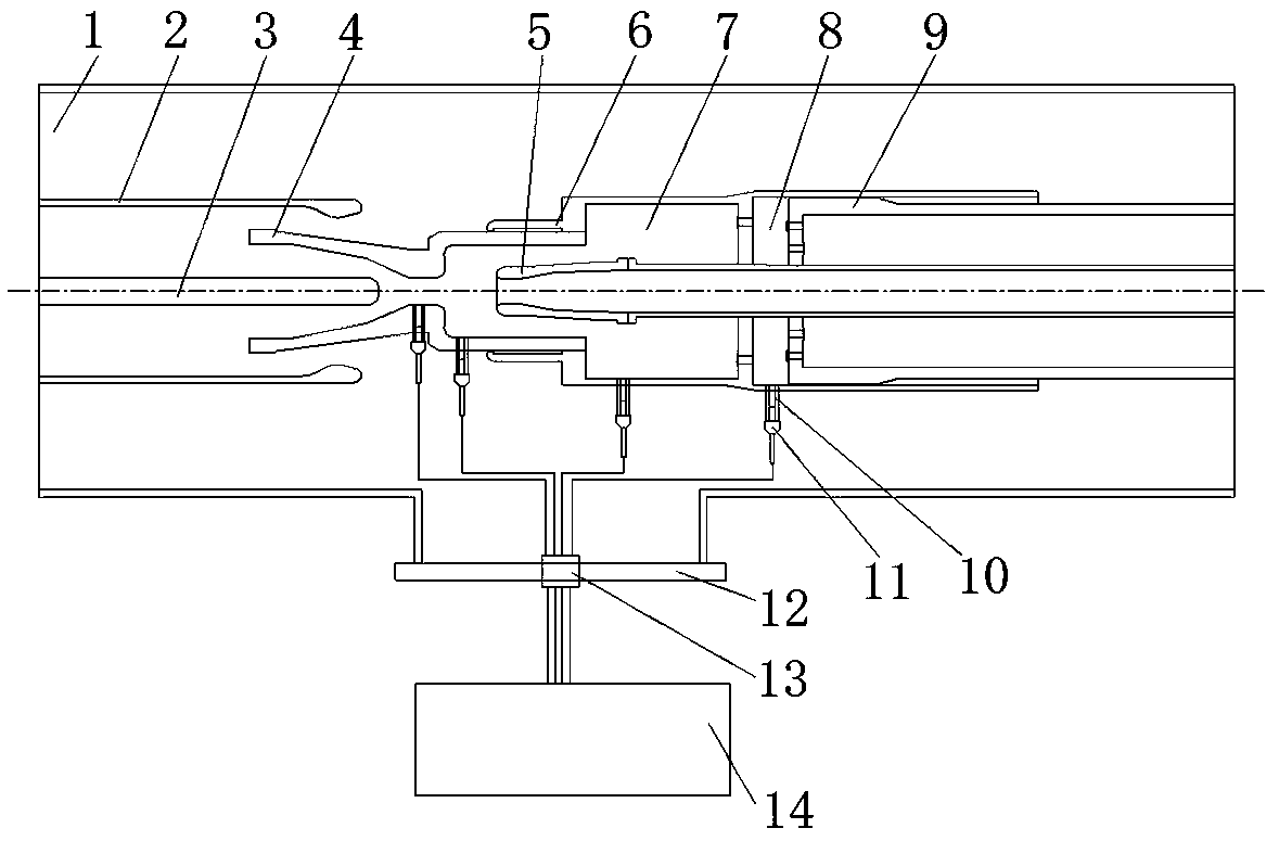
[0040] Such as figure 1 As shown, the device for measuring the pressure of the arc extinguishing chamber includes a measuring instrument 14 . The measuring instrument 14 is connected to a pressure sensor 11 through a wire, and the pressure sensor 11 is connected to the pressure guiding conduit 10 . One end of the pressure guide conduit 10 connected to the pressure sensor 11 is the sensor connection end, and the other end is the arc extinguishing chamber connection end.

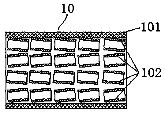
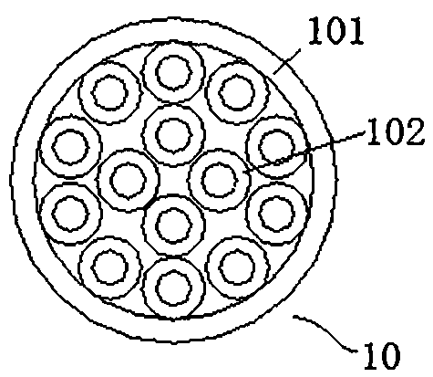
[0041] In this example, if figure 2 and image 3 As shown, the pressure guiding catheter 10 includes an outer catheter 101, and the outer catheter 101 is provided with sub-conductors 102. The sub-conductors 102 are arranged in multiple groups along the axial direction of the outer catheter 101, and each group of sub-conductors 102 is arranged along the radial direction of the outer catheter 101. There are multiple, so as to cover the cross-section of the outer catheter, thereby improving the damping effect,...

Embodiment 2

[0055] The difference from Example 1 is that the two ends of the outer conduit are not provided with stop sheets or stop nets. At this time, the sub-ducts need to be glued together first, and then glued into the outer conduit through the sub-ducts at the edge. To avoid prolapse of the sub-catheter.

Embodiment 3

[0057] The difference from Embodiment 1 is that the stop sheet is replaced by a stop net, such as a high temperature resistant metal net.


PUM


Abstract

The invention relates to an arc extinguish chamber pressure measuring device and a pressure guide pipe thereof, and the arc extinguish chamber pressure measuring device comprises a measuring instrument, a sensor and the pressure guide pipe, one end of the sensor is connected with the measuring instrument, and the other end of the sensor is connected with the pressure guide pipe; one end, far awayfrom the pressure sensor, of the pressure guide pipe is an arc extinguishing chamber connecting end, and the arc extinguishing chamber connecting end is used for being connected to an arc extinguishing chamber. A pressure guiding catheter comprises an outer catheter, at least two sets of sub-catheters are arranged in the outer catheter, and each set of sub-catheters are arranged in the axial direction of the pressure guiding catheter. Sub-conduits in each group of sub-conduits are arranged side by side and are fully distributed on the cross section of the outer conduit. At least two groups ofsub-conduits are arranged in the outer conduit of the pressure guide conduit, and each group of sub-conduits are arranged along the axial direction of the pressure guide conduit, so that pressure waves are transmitted to the pressure sensor through each sub-conduit in the outer conduit, the damping effect is improved, the oscillation is effectively inhibited, the influence of the existing air conduit on a measurement result is reduced, and an ideal measurement result is achieved.

Description

technical field [0001] The invention relates to a pressure measuring device for an arc extinguishing chamber and a pressure guiding conduit thereof. Background technique [0002] Measuring the pressure at different positions of the arc extinguishing chamber during the breaking process of the circuit breaker can help analyze the distribution of the airflow field in the arc extinguishing chamber and improve the design level of the circuit breaker. When measuring, due to the generation of arc, high temperature will be generated in the arc extinguishing chamber, and the current existing sensors cannot measure in such a high temperature environment, so the method of isolating the high temperature environment can only be adopted. [0003] The Chinese patent with the authorized notification number CN201177545Y discloses a device for measuring gas pressure characteristics at the nozzle orifice of a high-voltage circuit breaker with high current breaking. Avoid direct contact of the...

Claims


Application Information

Patent Timeline
Patent Type & Authority Applications(China)
IPC IPC(8): G01L19/06G01R31/327
CPCG01L19/06G01R31/327
Inventor 郭学凤沙云鹏姚永其左琪方昌健张楠楠
Owner PINGGAO GRP
Why Eureka
Try Eureka