Numerical control tool grinding machine

A tool grinder and machine tool technology, which is applied in the direction of manufacturing tools, grinding bed, grinding machine parts, etc., can solve the problems of small surface range of grinding tools, low level of grinding technology, errors in grinding data, etc., and achieve grinding The effect is smooth and uniform, the degree of automation and mechanization is high, and the grinding accuracy is improved.

Pending Publication Date: 2020-05-22
WUXI YUTIAN PRECISION TOOL
View PDF0 Cites 1 Cited by
  • Summary
  • Abstract
  • Description
  • Claims
  • Application Information

AI Technical Summary

Problems solved by technology

Therefore, in view of the errors in the grinding data and the low level of grinding technology in manual grinding, there is an automatic grinding machine that can automatically cut and grind the tool, which greatly reduces labor costs and improves work efficiency. However, the existing automatic grinding After the machine grinds one surface or one direction of the tool, it needs to be manually replaced to other surfaces. In addition, the range of the automatic grinding machine grinding tool surface is small, and it cannot be ground in all directions, resulting in low grinding accuracy and time-consuming more

Method used


Image

  • Numerical control tool grinding machine
  • Numerical control tool grinding machine
  • Numerical control tool grinding machine

Examples


Embodiment Construction

[0027] The present invention will be described in further detail below in conjunction with the accompanying drawings.

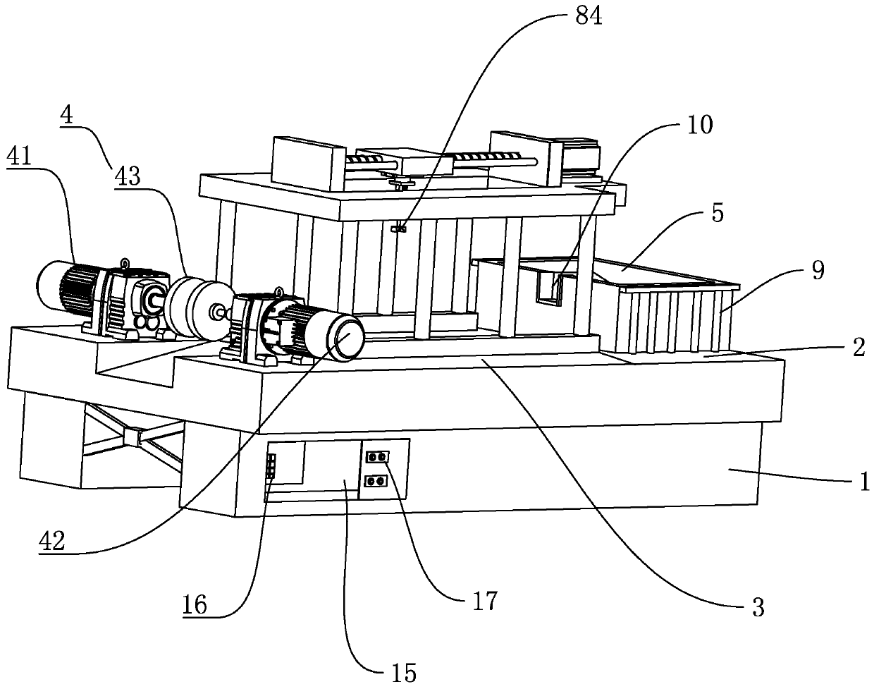
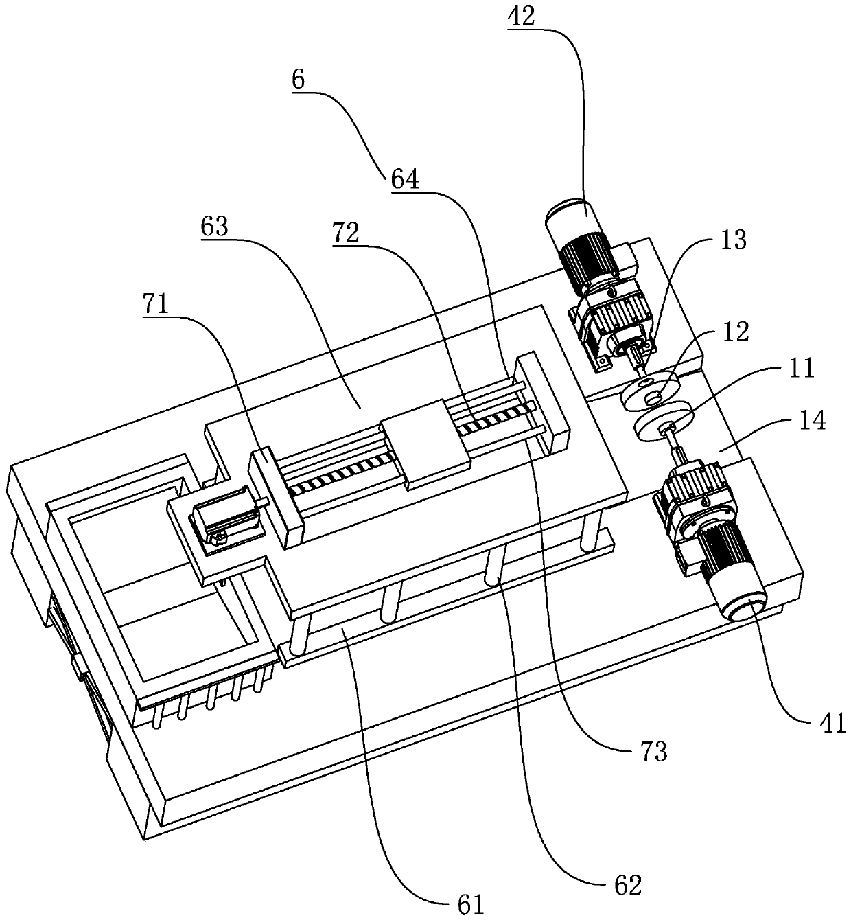
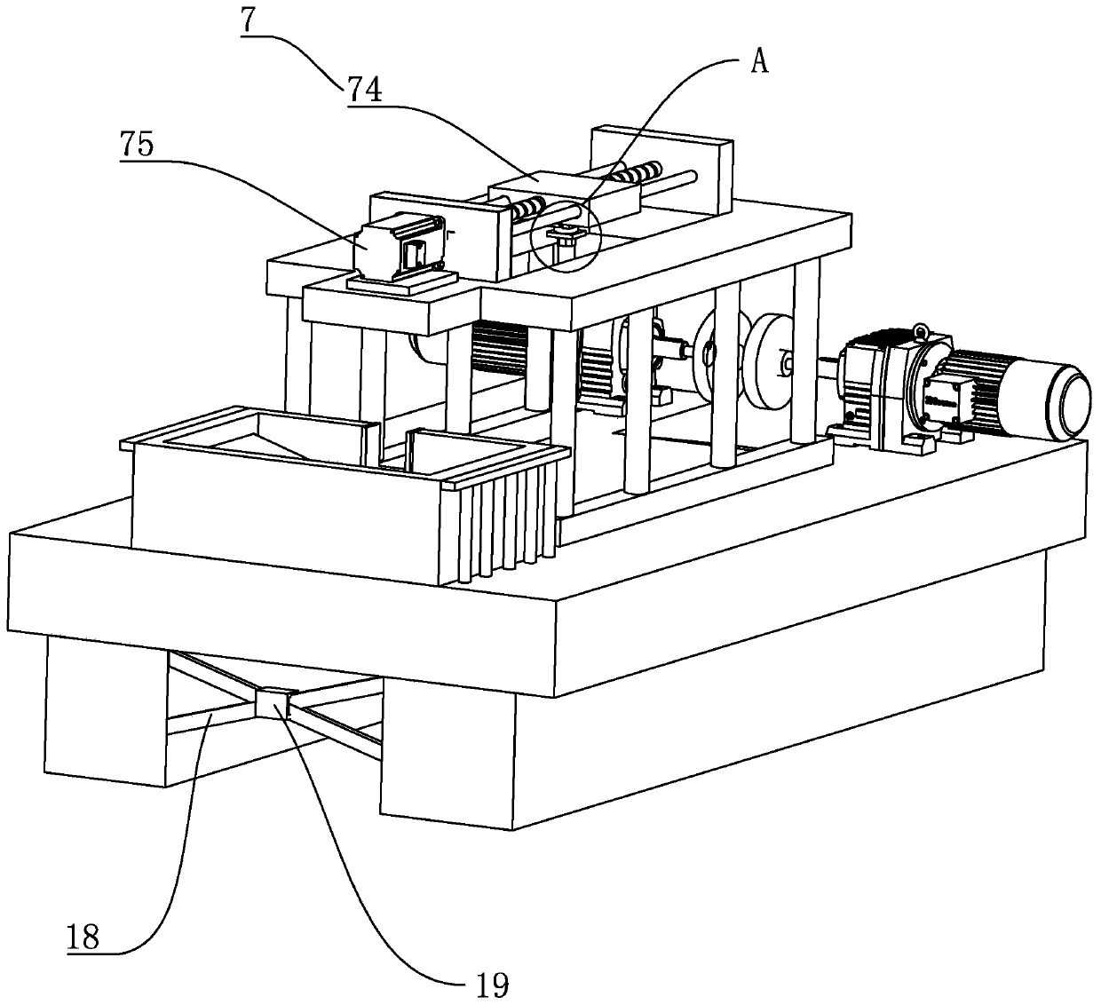
[0028] A CNC tool grinder, such as figure 1 , figure 2 and image 3 As shown, it includes a machine base 1 , a loading platform 2 arranged on the surface of the machine base 1 , a feeding platform 3 on one side of the loading platform 2 , and a grinding mechanism 4 on one side of the feeding platform 3 . The feeding platform 2 is provided with a thickened plate, the thickened plate is provided with a tool magazine 5, the surface of the tool magazine 5 is provided with a protective frame 9, and the side of the tool magazine 5 near the feeding platform 3 is provided with a discharge port 10, and the discharge port 10 one side is connected with the feeding mechanism 6 that is positioned on the feeding platform 3, and the feeding mechanism 6 includes the support plate 61 that is fixedly connected on the both sides of the feeding platform 3, and the vertical ve...


PUM


Abstract

The invention discloses a tool grinding machine, and aims to provide a numerical control tool grinding machine. According to the key points of the technical scheme, the numerical control tool grindingmachine comprises a machine tool base, a loading platform, a feeding platform and a grinding mechanism, wherein the loading platform is arranged on the surface of the machine tool base, the feeding platform is located on one side of the loading platform and the grinding mechanism is located on one side of the feeding platform, the loading platform is provided with a thickening plate, the thickened plate is provided with a tool magazine, the surface of the tool magazine is provided with a protective frame, one side, close to the feeding platform, of the tool magazine is provided with a discharge port, and one side of the discharging port is connected with a feeding mechanism located on the feeding platform. The feeding mechanism comprises supporting plates, vertical rods and driving plates, the supporting plates are fixedly connected to the two sides of the feeding platform, the vertically upward vertical rods are located on the supporting plates on the two sides, the driving plates are fixedly connected to the tops of the vertical rods on the two sides, a hollow groove is formed in the center of each driving plate, a reciprocating moving mechanism is arranged in the hollow grooves, the bottom of the reciprocating moving mechanism is connected with a grabbing mechanism, and the grinding mechanism comprises a motor set and a grinding abrasion wheel arranged on the output shaft of the motor set.

Description

technical field [0001] The invention relates to the field of cutter grinding equipment, in particular to a numerically controlled tool grinder. Background technique [0002] In the processing of parts, the processing of drilling and threading are the most common. The premise of thread processing is to drill the bottom hole first. At present, many knives are discarded or ground after being damaged. Manual grinding requires a high level of workers' skills, and the quality of grinding is also unstable. Therefore, in view of the errors in the grinding data and the low level of grinding technology in manual grinding, there is an automatic grinding machine that can automatically cut and grind the tool, which greatly reduces labor costs and improves work efficiency. However, the existing automatic grinding After the machine grinds one surface or one direction of the tool, it needs to be manually replaced to other surfaces. In addition, the range of the automatic grinding machine ...

Claims


Application Information

Patent Timeline
IPC IPC(8): B24B3/00B24B41/00B24B41/06B24B41/02B24B55/06B24B47/12B24B47/20
CPCB24B3/00B24B41/005B24B41/02B24B41/06B24B47/12B24B47/20B24B55/06
Inventor 朱胜雷庄云飞肖国民
Owner WUXI YUTIAN PRECISION TOOL
Why Eureka
Try Eureka