


Quick Research
Generate reliable direction feasibility study reports for your R&D in just a few steps.

Technical Q&A
Discover and master advanced knowledge NOW. Basics, ideas, possibilities, all at once.

Find Solutions
As an expert in R&D theories, this can generate solutions to your technical problems instantly.

Evaluate Feasibility
Analyze your overall solution with one click, know your potential R&D risks in advance.

Monitor Landscape
Get weekly tech updates, stay abreast of the latest tech innovations and key insights.
PTP clock synchronization system and clock synchronization method
A clock synchronization and master clock technology, applied in the direction of electrical components, automatic power control, etc., can solve the problems of affecting delay time, large signal influence, lag, etc., to reduce the difference in driving ability and ensure the effect of accuracy
- Summary
- Abstract
- Description
- Claims
- Application Information
AI Technical Summary
Problems solved by technology
Method used
Image

Examples
Embodiment 1
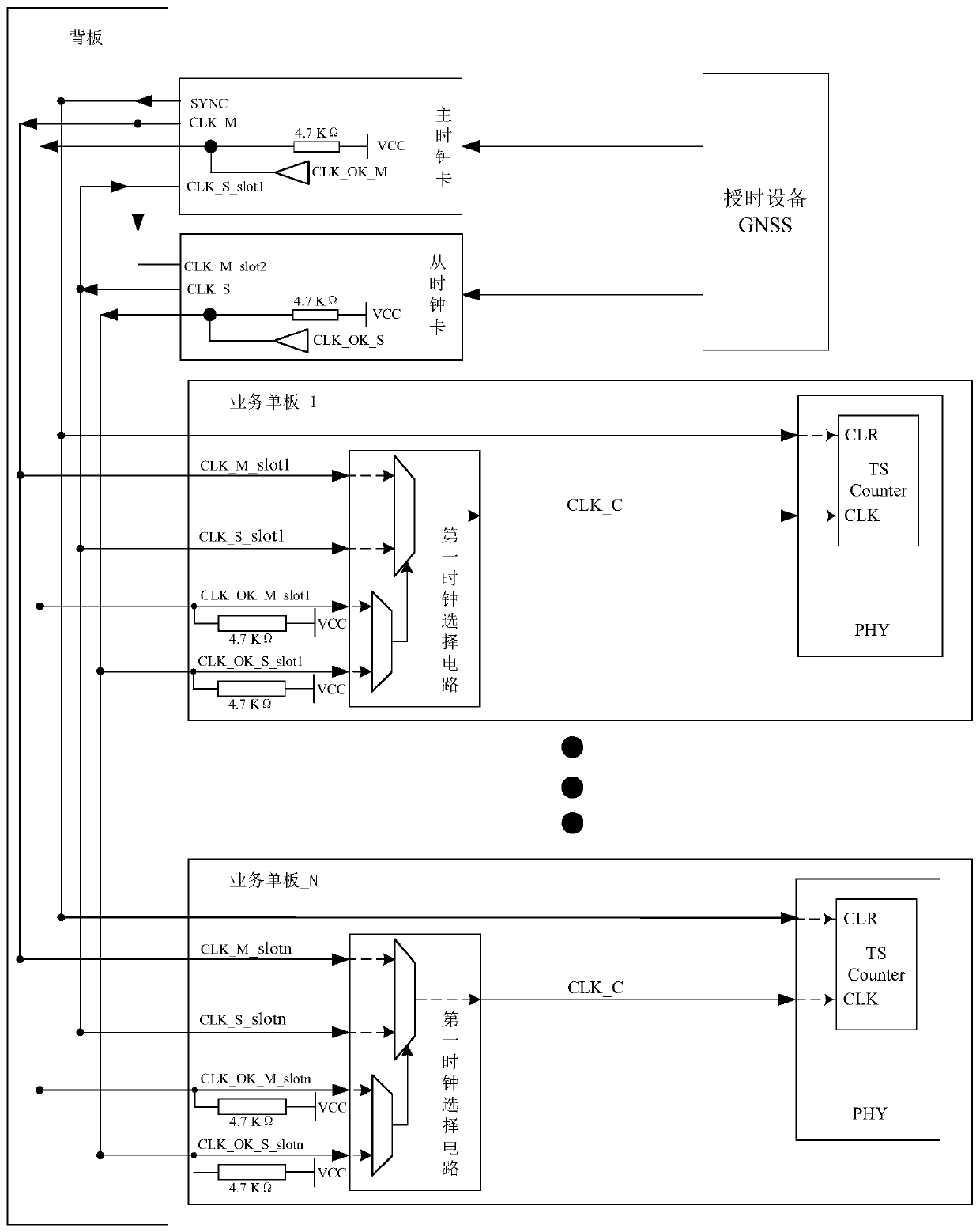
[0065] refer to figure 2 As shown, it is a schematic diagram of the principle of a PTP clock synchronization system. The clock synchronization system includes: a master clock board and a slave clock board that receive the GNSS clock signal of the same external timing device, and receive the master clock signal CLK_M and the slave clock output from the master clock board. Several business single boards of the slave clock signal CLK_S output by the board, and a backplane configured to form signal connection leads between the master clock board, the slave clock board and each business single board; wherein:
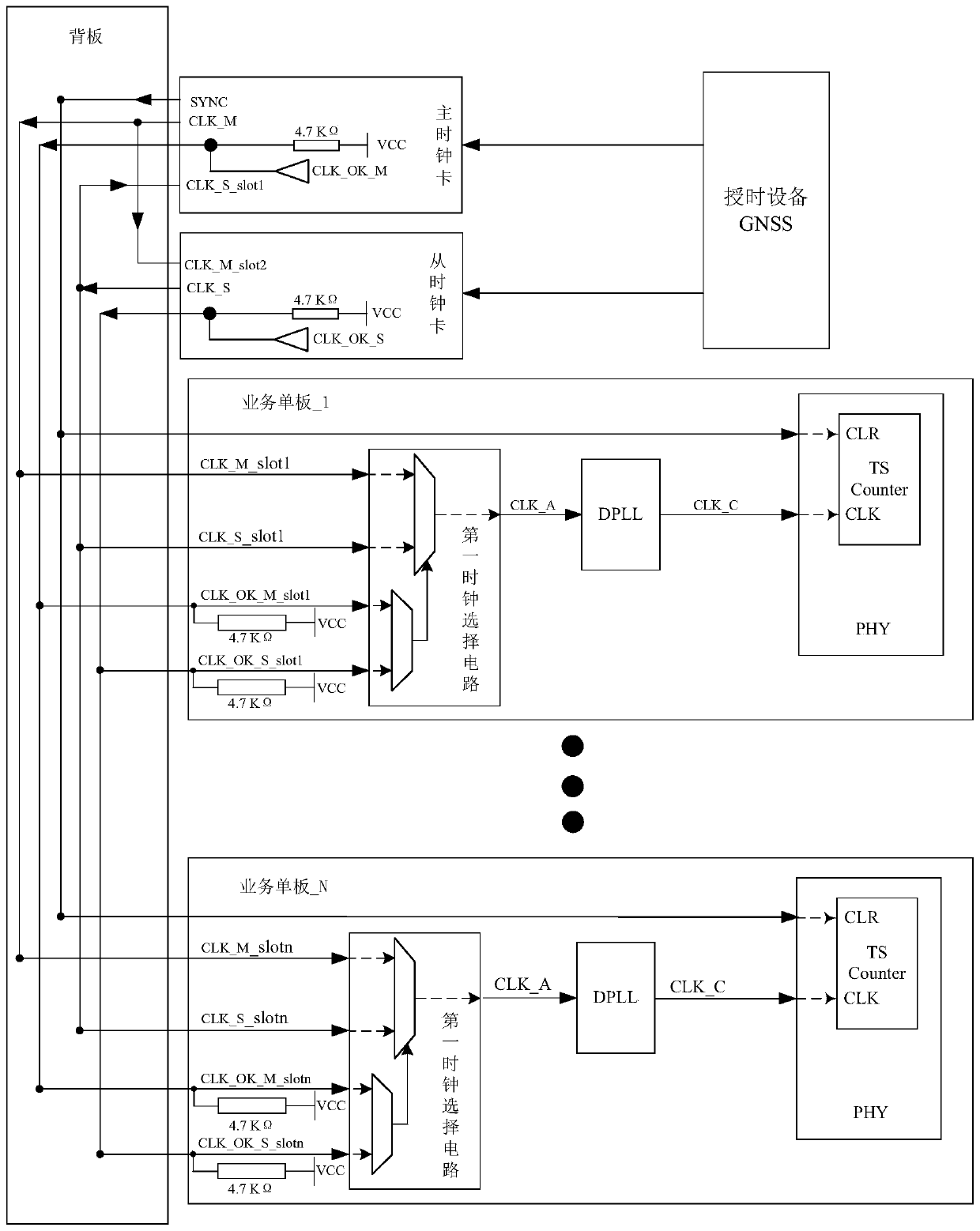
[0066] Each service single board is provided with a first clock selection unit, which determines that one of the clock signals is a working clock signal according to the current state of the master clock status signal and the slave clock status signal; and a digital phase-locked loop DPLL is used for receiving After the master clock signal and the working clock signal obtai...
Embodiment 2
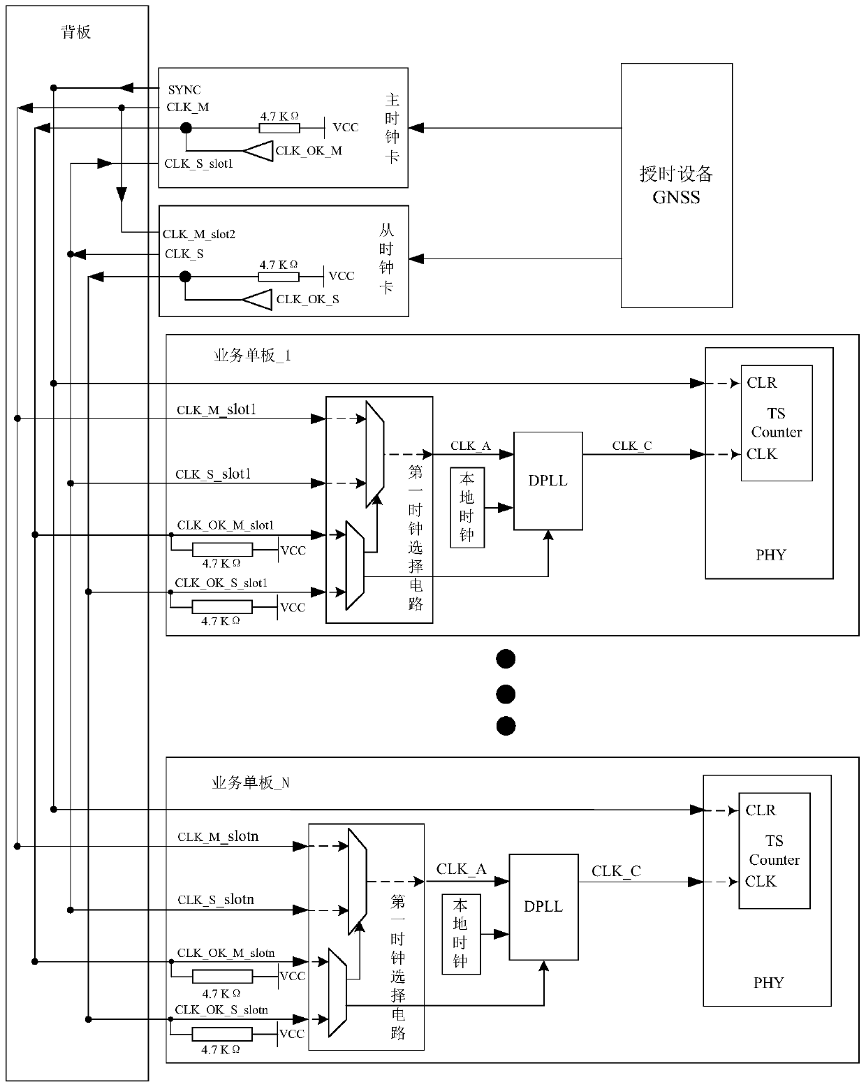
[0070] In the clock synchronization system provided by the above embodiments, as image 3 As shown, a local clock can also be set on each service board; typically, the local clock can be a temperature-compensated TCXO crystal oscillator with a frequency of 25MHZ, a voltage of 3.3V, and an accuracy of ±1PPM. For example, the China Electronics Technology Group Corporation No. TC3A2B02-25MHz launched by Fifty-four Research Institute.
[0071] When both the master clock card and the slave clock card are not ready due to some specific scenarios (for example, during the restart process of the PTP device, or the master clock card and the slave clock card are dialed out at the same time, etc.), obviously, the Both the master clock signal CLK_M and the slave clock signal CLK_S are invalid signals. At this time, the first clock selection unit outputs a second selection signal when judging that the master clock signal and the slave clock signal are invalid signals, and the After receivi...
Embodiment 3
[0073] In the above-mentioned first and second embodiments, when the digital phase-locked loop receives the clock signal, if it is found that there is a problematic clock signal, the current working state is automatically switched from the locked state to the holding state, and in this process, In order to ensure the accurate frequency of the output clock signal, the digital phase-locked loop may filter out unqualified pulses in this process, resulting in the loss of a small amount of pulses in the output clock. Thus, if Figure 4 As shown, a pulse regeneration unit is set between the digital phase-locked loop and the PHY chip to recover the missing pulse clock, so that the clock signal is completely restored to the expected value. Specifically, the pulse regeneration unit is specifically used for:
[0074] setting the first counter, and starting counting after initialization;
[0075] When it is judged that the output working clock signal after phase locking becomes a falli...
PUM
| Property | Measurement | Unit |
|---|---|---|
| Resistance | aaaaa | aaaaa |
Abstract
Description
Claims
Application Information
 - R&D Engineer
- R&D Manager
- IP Professional
- Industry Leading Data Capabilities
- Powerful AI technology
- Patent DNA Extraction
Browse by: Latest US Patents, China's latest patents, Technical Efficacy Thesaurus, Application Domain, Technology Topic, Popular Technical Reports.
© 2024 PatSnap. All rights reserved.Legal|Privacy policy|Modern Slavery Act Transparency Statement|Sitemap|About US| Contact US: help@patsnap.com