
Integral aluminum die body based on narrow expansion joint

An expansion joint and integral technology, which is applied in the fields of formwork/formwork/work frame, on-site preparation of building components, connectors of formwork/formwork/work frame, etc. On-site construction efficiency and other issues, to achieve the effect of guaranteed molding quality, easy support and dismantling construction, and easy partial replacement

Pending Publication Date: 2020-05-19
广东龙越建筑工程有限公司
View PDF0 Cites 1 Cited by
  • Summary
  • Abstract
  • Description
  • Claims
  • Application Information

AI Technical Summary

Problems solved by technology

For buildings with high-rise shear wall structures, due to the narrow expansion joints (less than 300mm), it is very difficult to disassemble the post-cast wall formwork at the expansion joints, which increases the difficulty of construction management and reduces the efficiency of on-site construction
[0003] Moreover, the turnover times of the wooden formwork are small, the cost is high, and the formwork cannot be disassembled; the steel formwork is formed as a whole, can be used repeatedly, and the size is accurate, but the input cost is high, the turnover rate of the steel formwork is low, and the steel formwork is relatively heavy, which requires an increase in the cost of the tower crane, and Not compatible with aluminum mold system

Method used


Image

  • Integral aluminum die body based on narrow expansion joint
  • Integral aluminum die body based on narrow expansion joint
  • Integral aluminum die body based on narrow expansion joint

Examples


Embodiment

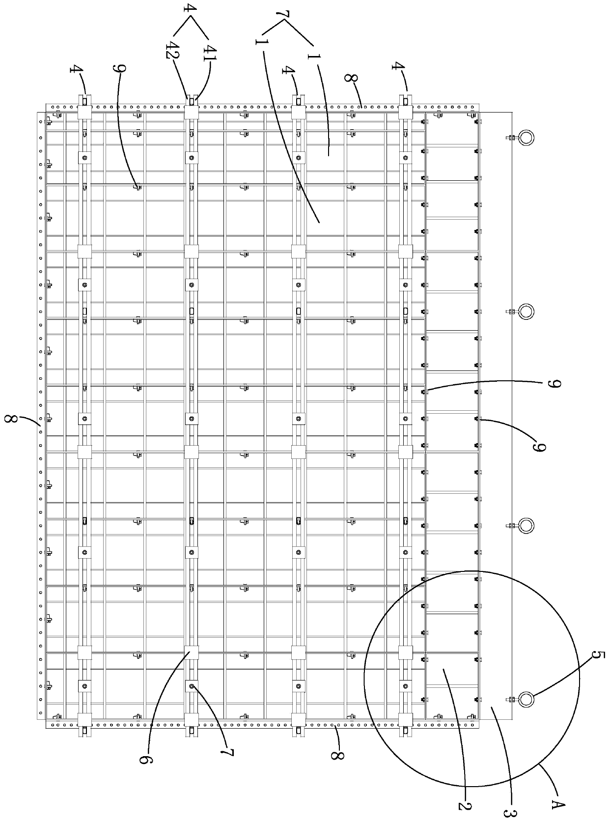
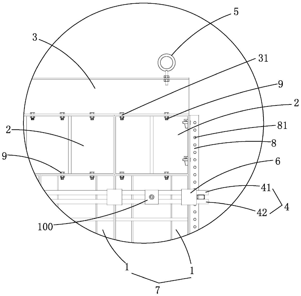
[0022] Example, combined with Figure 1 to Figure 3 As shown, an integral aluminum formwork body based on narrow expansion joints includes an aluminum formwork 1 , a K plate 2 , a profile steel 3 , a back flute 4 , a lifting ring 5 , a back flute buckle 6 and a tension screw 100 .

[0023] The aluminum formwork 1 is arranged according to the drawing size, the aluminum formwork 1 and the aluminum formwork 1 are connected, and the aluminum formwork 1 and the aluminum formwork 1 are locked by pins 9 to form a wallboard 7 .

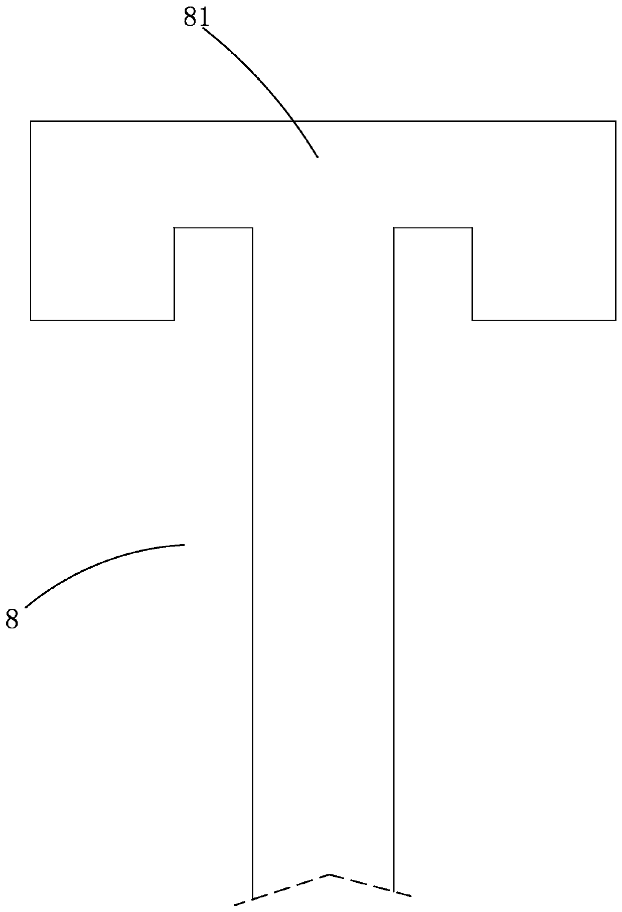
[0024] The left side, the bottom and the right side of the wallboard 7 are all provided with angled aluminum 8 , and the angled aluminum 8 is spaced with bolt holes 81 along its length direction.

[0025] The K board 2 is arranged on the top of the wall board 7 and connected to the wall board 7 , and the K board 2 and the aluminum formwork 1 are locked by pins 9 .

[0026] The shaped steel 3 is channel steel, the shaped steel 3 is arranged above the K plate ...


PUM


Abstract

The invention relates to an integral aluminum die body based on a narrow expansion joint. The integral aluminum die body comprises aluminum formworks, a K plate, profile steel, back ridges and hangingrings, wherein the aluminum formworks are arranged according to the drawing size, the aluminum formworks are connected to form a wallboard, and angle aluminum is arranged on the left side, the bottomand the right side of the wallboard; the K plate is arranged on the top of the wallboard and connected with the wallboard, the profile steel is arranged above the K plate and connected with the K plate, and hanging holes are formed in the upper end of the profile steel at intervals in the length direction of the profile steel; and the hanging rings are arranged on the corresponding hanging holesin a sleeved mode, the back ridges are arranged at intervals in the height direction of the wall plate, a split bolt is arranged between the wall plate and the back ridges, and the wall plate and theback ridges are locked together through the split bolt. The aluminum formworks, the back ridges, the profile steel and the like are integrally hoisted into a deformation joint to be fixed after beingassembled in a ground working area, and when the formworks are disassembled, the whole aluminum formworks can be hoisted and disassembled through a tower crane only by disassembling the split bolt, sothat the whole formwork system is efficient and rapid in construction.

Description

technical field [0001] The invention relates to the construction field, in particular to an integral aluminum formwork body based on narrow expansion joints. Background technique [0002] With the acceleration of urbanization and the maturity of technology, aluminum formwork construction has become the development trend of the construction industry. Compared with traditional wood formwork, it can improve the efficiency of project construction, improve the quality of project construction, ensure project quality, and ensure construction safety. The advantages of reducing energy consumption and carbon emissions, green and sustainable. However, due to the increasingly complex shape and volume of modern buildings, in order to ensure the safe use of buildings, many buildings are often designed with expansion joints. For buildings with high-rise shear wall structures, due to the relatively narrow expansion joints (less than 300mm), it is very difficult to disassemble the post-cast...

Claims


Application Information

Patent Timeline
Patent Type & Authority Applications(China)
IPC IPC(8): E04G11/08E04G11/12E04G17/065E04G17/04
CPCE04G11/085E04G11/12E04G17/042E04G17/0652E04G2017/008
Inventor 田岳龙匡建初鲁海徐书峰谭国进湛振泳
Owner 广东龙越建筑工程有限公司
Learn More