Intelligent remote-control driverless ditching machine
An unmanned, intelligent remote control technology, applied in the direction of earth movers/shovels, signal transmission systems, instruments, etc., can solve the problem of difficult to control the position and attitude of the cutting disc, avoid danger, have more degrees of freedom, and simplify Controlling the effect of difficulty
- Summary
- Abstract
- Description
- Claims
- Application Information
AI Technical Summary
Problems solved by technology
Method used
Image


Examples
Embodiment 1
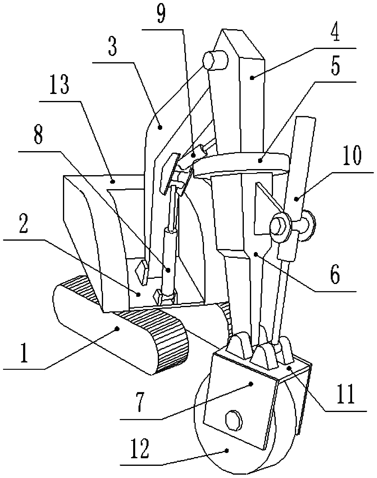
[0026] Embodiment 1 is basically as attached figure 1 Shown:
[0027]The intelligent remote-controlled unmanned trenching machine includes a traveling mechanism 1, which adopts a steel crawler chassis, and the traveling mechanism 1 is connected to the organic platform 2 by rotating a turntable bearing, and the body platform 2 is a rectangular steel plate. The middle position is also fixed with a first drive motor with bolts, the first drive motor drives the body platform 2 to rotate, and the first drive motor adopts the ATS 3306D excavator rotary hydraulic motor reducer assembly. One end of the body platform 2 is fixed with a hydraulic station by bolts, and the other end of the body platform 2 is also hinged with a boom 3, the swing plane of the boom 3 is perpendicular to the body platform 2, and the boom 3 and the body platform 2 are fixedly connected. A driving cylinder 8, the two ends of the first driving cylinder 8 respectively hinge the boom 3 and the body platform 2, an...
Embodiment 2
[0039] Embodiment 2 is substantially the same as Embodiment 1, and the only difference is that the hinge axis of the rotating arm 6 and the end support is parallel to the rotation axis of the cutting disc 12 . When the end support swings, the cutting disc 12 swings left and right around the shaft hinged by the rotating arm 6 and the end support, and the cutting disc 12 can be made perpendicular to the ground by adjusting the swing of the end support, so that the cutting disc 12 is perpendicular to the ground for cutting operations, which is convenient for cutting out Vertically downward groove.
[0040] The outer wall of the fixed bracket is also fixed with a second inclination sensor with screws, which is connected to the controller through RS485 communication. The second inclination sensor also adopts the LCA310T uniaxial voltage output type inclination sensor. The controller collects the signal of the second inclination sensor to obtain the second inclination value of the c...
Embodiment 3
[0044] Embodiment 3 is roughly the same as Embodiment 1, except that the outer wall of the side plate 7 of the end bracket is screwed with an acceleration sensor, the acceleration sensor is connected to the controller through communication, and the acceleration sensor is a Huining S31D02 piezoelectric acceleration sensor. When the cutting disc 12 is excavating, it may hit hard objects, such as stones, hard cement blocks, etc., and the impact teeth constantly hit the hard objects, and the cutting disc 12 will be subjected to a large continuous impact, which can be detected by the acceleration sensor fixed on the end bracket. Measure the impact.
[0045] The controller collects the vibration signal of the acceleration sensor, the analysis module obtains the vibration signal, and monitors the amplitude of the vibration signal, and the frequency threshold and the amplitude threshold are stored in the analysis module. When the amplitude of the vibration signal is greater than the a...
PUM
 Abstract
Description
Claims
Application Information
 - R&D
- Intellectual Property
- Life Sciences
- Materials
- Tech Scout
- Unparalleled Data Quality
- Higher Quality Content
- 60% Fewer Hallucinations
Browse by: Latest US Patents, China's latest patents, Technical Efficacy Thesaurus, Application Domain, Technology Topic, Popular Technical Reports.
© 2025 PatSnap. All rights reserved.Legal|Privacy policy|Modern Slavery Act Transparency Statement|Sitemap|About US| Contact US: help@patsnap.com