
Optical cable and electric cable easy to strip

An optical cable and stripping technology, applied in the field of optical cables and cables that are easy to open and strip, can solve the problems of optical fiber breakage, inconvenient heat dissipation, trouble, etc.

Inactive Publication Date: 2020-05-15
常熟虞星光电科技有限公司
View PDF0 Cites 1 Cited by
  • Summary
  • Abstract
  • Description
  • Claims
  • Application Information

AI Technical Summary

Problems solved by technology

[0002] The People’s Republic of China’s communication industry standard YD / T901 specifies the layer-stranded optical cable. The core of the layer-stranded optical cable is usually twisted by multiple loose tubes around the central strength member, and the loose tube has a wrapping material outside. There is an optional protective layer or sheath outside the cable core. The wrapping material is used to stabilize the cable core structure and prevent the loose tube from falling apart during manufacture and use. However, the existence of the cable core often causes the following defects: (1 ) The thinner loose tube is broken, which affects the performance of the optical fiber and even breaks the fiber; (2) When the temperature is high or low, the loose tube is often damaged due to the inconsistent shrinkage of the loose tube and the wrapping material , so that the performance of the optical fiber is affected, and even the optical fiber is broken; (3) when stripping, it is necessary to cut the spiral-coated packing material longitudinally. On the one hand, the stripping speed is slow and the efficiency is low; Otherwise, it will cause a long-term loose state; (4) The purchase, storage, and use of the dressing materials themselves all require cost, which makes the cost of the product higher
[0004] The skeletal ribbon optical cable stipulated in the Communication Industry Standard YD / T981.1 of the People's Republic of China has a skeleton and a skeleton groove around the skeleton. The optical fiber ribbon is placed in the skeleton groove, and the coating material is used to cover the skeleton groove so that It does not escape during use. Due to the existence of the periphery, the skeleton groove cannot be too deep. If it is too deep, the opposite skeleton groove cannot exist, and it reaches the center at most, which limits the number of optical fiber ribbons in the skeleton groove.
[0005] The cables in the prior art need to peel off the sheath and the inner protective layer when stripping, which is quite troublesome, and the layers of coating are not only inconvenient for stripping, but also inconvenient for heat dissipation

Method used

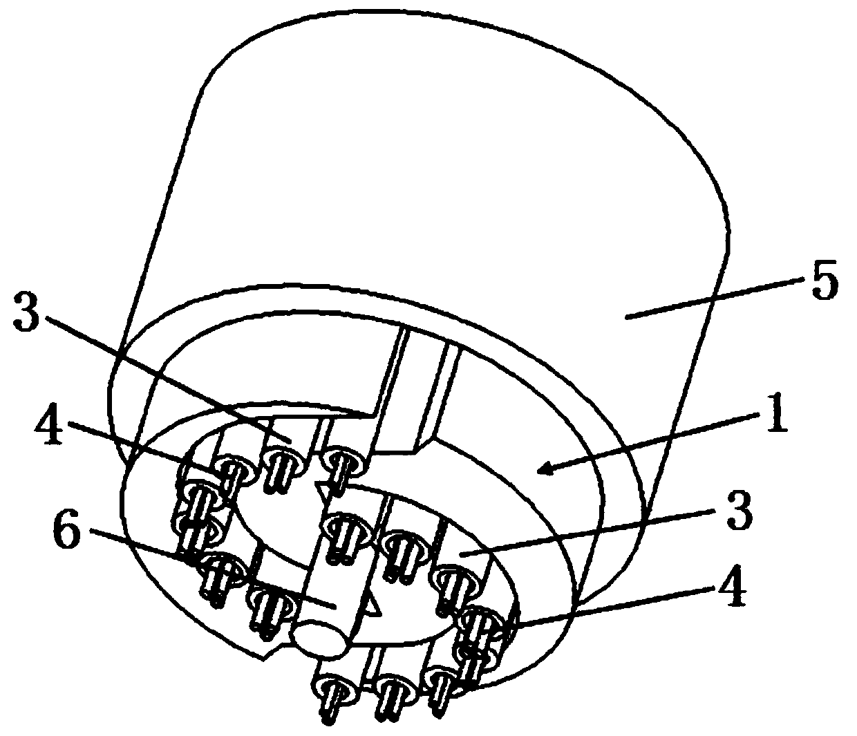

Image

  • Optical cable and electric cable easy to strip
  • Optical cable and electric cable easy to strip
  • Optical cable and electric cable easy to strip

Examples


Embodiment 1

[0046] please see Figure 1 to Figure 4 , and see Figure 5 to Figure 9 , an optical cable that is easy to peel, has a support body 1, an outer sheath 5 covering the support body, a reinforcement member 6 located in the center of the support body, and a plurality of loose tubes 3 located in the support body, each loose There is an optical fiber 4 in the sleeve; it is characterized in that the stent body 1 is composed of a first stent body 11, a second stent body 12, and a body connecting portion 13, and the first stent body 11 is located on the left side of the body connecting portion 13, The second bracket body 12 is located on the right side of the body connecting part 13, the lower right part of the first bracket body 11 is connected with the lower part of the body connecting part 13, and the upper left part of the second bracket body 12 is connected with the upper part of the body connecting part 13. , the body connecting portion 13 is formed by combining two semi-cylindr...

Embodiment 2

[0052] please see Figure 10 with Figure 11 , and refer to Figure 1 to Figure 9 , a cable that is easy to peel, has a support body 1, an outer sheath 5 covering the support body, a reinforcement member 6 located in the center of the support body, a plurality of first power transmission units 21 located in the support body, and a plurality of first power transmission units 21 located in the support body. Two power transmission units 22, multiple third power transmission units 23, and multiple fourth power transmission units 24; it is characterized in that the support body 1 is composed of a first support body 11, a second support body 12, and a body connecting part 13. A bracket body 11 is positioned at the left side of the body connecting portion 13, and a second bracket body 12 is positioned at the right side of the body connecting portion 13. The upper left part is connected with the upper part of the main body connecting part 13, and the main body connecting part 13 is ...

Embodiment 3

[0057] please see Figure 12 to Figure 14 , and refer to Figure 1 to Figure 11 , an optical cable that is easy to peel, has a support body 1, an outer sheath 5 covering the support body, a reinforcement member 6 located in the center of the support body, a first power transmission unit 21 and a second power transmission unit 22 located in the support body , a plurality of loose tubes 3, optical fibers 4 positioned in the loose tubes; it is characterized in that the support body 1 is composed of a first support body 11, a second support body 12, and a body connecting portion 13, and the first support body 11 is located on the left side of the body connecting portion 13, and the second bracket body 12 is positioned on the right side of the body connecting portion 13. The lower right part of the first bracket body 11 is connected with the lower part of the body connecting portion 13, and the upper left part of the second bracket body 12 is connected to the bottom of the body con...


PUM


Abstract

The invention belongs to the technical field of cables, and relates to an optical cable easy to strip. The optical cable is provided with a support body, an outer sheath, a reinforcer, a loose tube and optical fibers in the loose tube, and is characterized in that the support body is composed of a first support body, a second support body and a body connecting part; the first support body is located on the left of the body connecting part; the second support body is located on the right of the body connecting part; the lower right part of the first support body is connected with the lower partof the body connecting part; the upper left part of the second support body is connected with the upper part of the body connecting part; the body connecting part is formed by combining plane parts of two semi-cylinders in an opposite and staggered mode, the outer edge of the second support body is a part of the surface of the cylinder, and the outer edge of the first support body and the outer edge of the second support body are located on the same cylinder surface. The invention further discloses a cable easy to strip. The optical cable and the cable have the following main beneficial effects: the structure is more compact, the weight is lighter, the cost is lower, the stripping and manufacturing are easier, and the percent of pass is higher.

Description

technical field [0001] The invention belongs to the technical field of optoelectronics and cables, and in particular relates to an easy-to-stripping optical cable and cable. Background technique [0002] The People’s Republic of China’s communication industry standard YD / T901 specifies the layer-stranded optical cable. The core of the layer-stranded optical cable is usually twisted by multiple loose tubes around the central strength member, and the loose tube has a wrapping material outside. There is an optional protective layer or sheath outside the cable core. The wrapping material is used to stabilize the cable core structure and prevent the loose tube from falling apart during manufacture and use. However, the existence of the cable core often causes the following defects: (1 ) The thinner loose tube is broken, which affects the performance of the optical fiber and even breaks the fiber; (2) When the temperature is high or low, the loose tube is often damaged due to the ...

Claims


Application Information

Patent Timeline
IPC IPC(8): G02B6/44H01B7/00H01B7/38
CPCG02B6/4429H01B7/00H01B7/38
Inventor 沈群华
Owner 常熟虞星光电科技有限公司
Learn More