Real-time forced belt deviation correcting device

A deviation correction device and belt technology, which is applied in the direction of conveyor control devices, transportation and packaging, conveyor objects, etc., can solve the problems of not eliminating the safety risk of belt deviation, scratches, wear and even damage, and belt life reduction, so as to achieve deviation correction Strong strength, high deviation correction strength, and the effect of protecting damage

Pending Publication Date: 2020-05-15
于重梁
View PDF0 Cites 0 Cited by
  • Summary
  • Abstract
  • Description
  • Claims
  • Application Information

AI Technical Summary

Problems solved by technology

As a result, the belt deviates repeatedly, and the deflection-correcting idler sets repeatedly rectify the deflection, but the belt is not actually rectified, and the safety risk of scratches, wear and even damage caused by the deflection of the belt is not eliminated, and the life of the belt is significantly reduced

Method used


Image

  • Real-time forced belt deviation correcting device
  • Real-time forced belt deviation correcting device
  • Real-time forced belt deviation correcting device

Examples


Embodiment 1

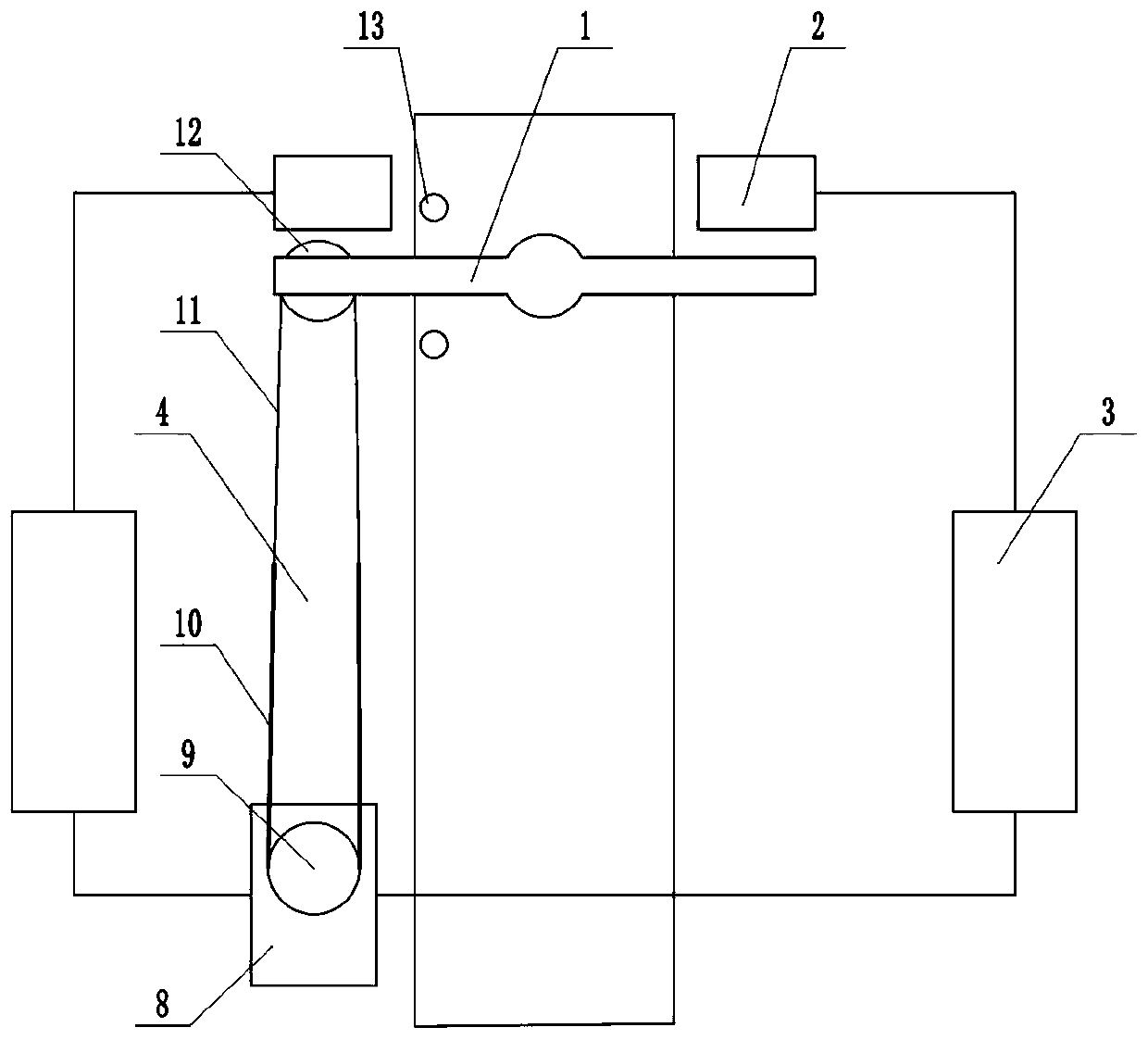
[0024] Please see attached figure 1 to attach image 3 As shown, a real-time forced belt deviation correction device includes a deviation adjustment idler group 1, a trigger mechanism 2, a signal transmission circuit 3 and an actuator 4; the three deviation adjustment idler groups 1 are installed on a belt conveyor, each One trigger mechanism 2 is respectively installed on the left and right sides of the deflection adjustment idler group 1; each trigger mechanism 2 controls the actuator 4 through a signal transmission circuit 3, and the actuator 4 controls the Adjust the movement of idler roller group 1.

[0025] The signal transmission circuit 3 includes a delay switch 5, a time relay 6 and a contactor 7; the trigger mechanism 2 is electrically connected to the input end of the delay switch 5, and the delay switch 5, the time relay 6 and the contactor 7 Electrically connected in turn, the output end of the contactor 7 is electrically connected to the actuator 4 .

[0026] ...

Embodiment 2

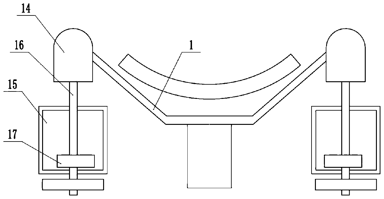
[0033] Please see attached figure 1 , attached figure 2 And attached Figure 4 As shown, embodiment 2 is on the basis of embodiment 1, and also includes a signal conversion switch 18 adapted to the oval cam 17; the signal conversion switch 18 is installed in the protective shell 15, and is connected with The two signal transmission circuits 3 are electrically connected.

[0034] How to use: When the working section of the belt conveyor runs towards the head of the belt conveyor, if the belt deviates seriously to the right, first scratch the right side of the belt conveyor as attached figure 1 to attach image 3The vertical rod 14 in the shown signal conversion device drives the vertical rod 16 to turn to the front right through the set angle through the vertical stick 14, and the elliptical cam 17 installed in the vertical rod 16 also turns to the set angle, And trigger the conduction to the right delay switch 5. After the right delay switch 5 receives the current signal,...


PUM

PropertyMeasurementUnit
Diameteraaaaaaaaaa

Abstract

The invention discloses a real-time forced belt deviation correcting device. The real-time forced belt deviation correcting device comprises deviation adjusting carrier roller sets, a triggering mechanism, a signal transmission circuit and an executing mechanism. The belt deviation correcting device has the beneficial effects that firstly, the belt deviation correcting device can adjust the powersupply time of a time relay in time according to actual needs so that a given value of a deviation correcting angle every time can be changed in time, and after deviation correction every time, the deviation correction can still be continued when a belt deviates again until the belt runs normally; and secondly, a limiting switch is installed on the belt deviation correcting device, when the deviation correcting angle is greater than 15 degrees, the corresponding limiting switch acts, a contactor disconnects a loop, and the deviation correcting device stops running so as to protect the deviation correcting device and a belt conveyor from being damaged; and the belt deviation correcting device adopts the three deviation adjusting carrier roller sets for correcting deviation at the same time,the deviation correcting strength is large, the deviation correcting strength is high, the unexpected effect on belt deviation control is achieved, and the real-time deviation correction and the accurate deviation correction are achieved in one step.

Description

technical field [0001] The invention relates to the field of electric power technology, in particular to a real-time forced belt deviation correction device. Background technique [0002] At present, the deviation correction devices used in the power system and belt conveyor systems in other industries are all mechanical deviation correction devices, that is, relying on the deviation of the belt to generate thrust to the deviation correction device on the protruding side, so that the rotation mechanism of the deviation correction device rotates an angle to correct the deviation of the belt. partial purpose. The currently known correction devices are: trough-shaped self-aligning roller group, conical lower-centering roller group, conical upper-centering roller group, flat upper-centering roller group, flat-down centering roller group, two-way reversible automatic adjustment Center idler set, friction down-adjusting center idler set, friction up-adjusting center idler set, st...

Claims


Application Information

Patent Timeline
IPC IPC(8): B65G15/64B65G39/16B65G43/02
CPCB65G15/64B65G39/16B65G43/02
Inventor 于重梁
Owner 于重梁
Why Eureka
Try Eureka