
Patsnap Eureka
For R&D, Patsnap Eureka makes reading and utilizing patents & technical documents easy.
Patsnap Eureka AIR
Designed for self-driven R&D workflows. Generate viable solutions, solve complex R&D challenges, empower your innovation with AI.

Patsnap Eureka Materials
Designed for material experts only. Revolutionize your material R&D, from search, analyze, to developing new materials.

TechResearch
Generate reliable direction feasibility study reports for your R&D in just a few steps.

TechSeek
Discover and master advanced knowledge NOW. Basics, ideas, possibilities, all at once.

TechMind
As an expert in R&D Theories, TechMind can generates customized viable solutions instantly.

TechRisk
Analyze your overall solution with one click, know your potential R&D risks in advance.

TechMonitor
Get weekly tech updates, stay abreast of the latest tech innovations and key insights.
Chirped pulse amplification laser device with targeting returned light detecting function and detection method of chirped pulse amplification laser device
A laser device and chirped pulse technology are applied in the field of chirped pulse amplifying laser devices, which can solve the problems of difficulty in detecting return light, separation of incident light and return light, etc., so as to increase the detection ability and protect the effect of damage.
- Summary
- Abstract
- Description
- Claims
- Application Information
AI Technical Summary
Problems solved by technology
Method used
Image

Examples
Embodiment 1
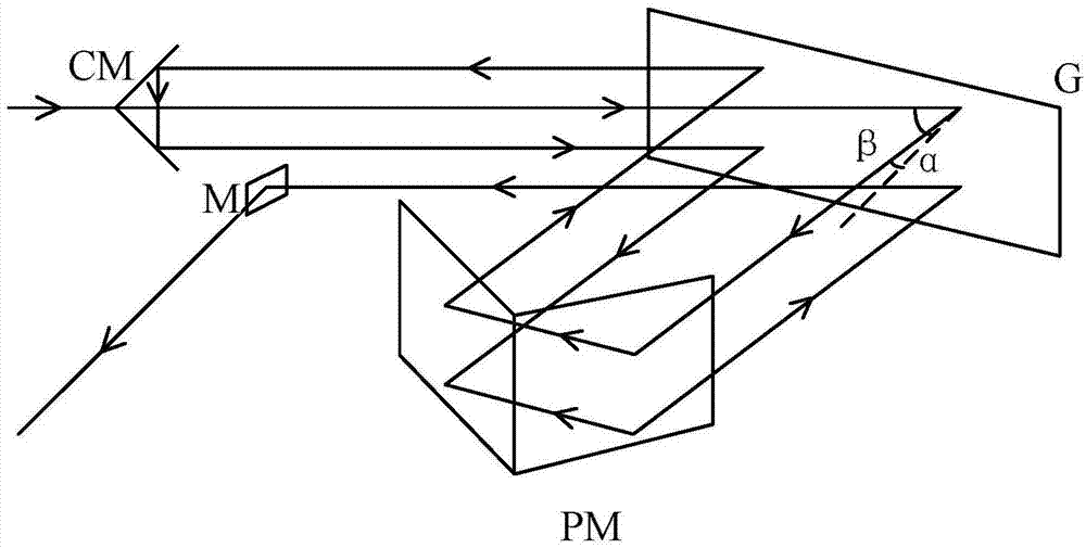
[0041] Such as figure 2 As shown, in this embodiment, the compressor adopts a single grating G, and cooperates with a horizontal right-angle mirror PM, a right-angle mirror CM and a mirror M to realize that the beam passes through the grating four times; the high-energy laser beam output from the amplifier enters To the compressor, it first enters the upper half area of the grating G, the incident angle of the beam is β, the grating G diffracts the incident laser light, and the first-order diffracted light with a diffraction angle of α enters the horizontal right-angle mirror PM, and the beam passes through the horizontal right-angle mirror After the PM is reflected, it emerges in the same horizontal plane along the opposite direction of incident on the horizontal right-angle reflector, and the outgoing light is translated in the horizontal direction relative to the incident light on the horizontal right-angle reflector, and the outgoing light is incident on the upper half o...
Embodiment 2
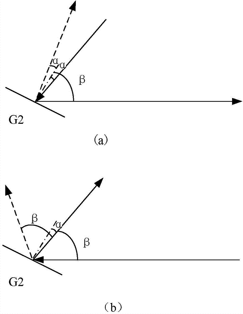
[0044] Such as Figure 4 As shown, in this embodiment, the compressor adopts double gratings, that is, the first grating G1 and the second grating G2 with the same parameters, and cooperates with a right-angle mirror CM and a mirror M to realize that the light beam passes through the grating four times; from The high-energy laser beam amplified by the amplifier is input into the compressor, and firstly enters the upper half area of the first grating G1, the beam incident angle is β, the first grating diffracts the incident laser light, and the first-order diffracted light with the diffraction angle α is reflected to In the upper half area of the second grating, the first grating is parallel to the second grating. At this time, the incident angle of the light beam incident on the second grating G2 is α, and the first-order diffracted light with a diffraction angle of β is incident on the right-angle mirror. After being reflected by the right-angle mirror CM, it will exit pa...
Embodiment 3
[0069] In this example, if Figure 10 As shown, the compressor uses four first to fourth gratings G1 to G4 with the same parameters to realize the beam passing through the gratings four times; the high-energy laser beam amplified by the amplifier enters the compressor, and first enters the first grating G1, The beam incident angle is β, and the first-order diffracted light with a diffraction angle of α enters the second grating G2, the first grating and the second grating are parallel, and the first-order diffracted light of the second grating enters the third grating G3, and the incident angle is β, The first-order diffracted light with a diffraction angle of α enters the fourth grating G4, the third grating is parallel to the fourth grating, and the first-order diffracted light of the fourth grating is output as the main optical path of the compressor. All the above rays are in the same horizontal plane. The return light passes through the fourth to the first grating in tur...
PUM
 Abstract
Description
Claims
Application Information
 - R&D Engineer
- R&D Manager
- IP Professional
- Industry Leading Data Capabilities
- Powerful AI technology
- Patent DNA Extraction
Browse by: Latest US Patents, China's latest patents, Technical Efficacy Thesaurus, Application Domain, Technology Topic, Popular Technical Reports.
© 2024 PatSnap. All rights reserved.Legal|Privacy policy|Modern Slavery Act Transparency Statement|Sitemap|About US| Contact US: help@patsnap.com