
Analog delay line receiver and implementation method thereof

A receiver and delay line technology, applied in the field of electronic warfare, can solve the problems of digital single-bit receiver two-tone dynamic and multi-tone dynamic difference, limited instantaneous dynamic range, missed detection, etc., to solve the problem of interpulse noise error detection. Effect

Inactive Publication Date: 2020-05-12
南京航天工业科技有限公司
View PDF0 Cites 1 Cited by
  • Summary
  • Abstract
  • Description
  • Claims
  • Application Information

AI Technical Summary

Problems solved by technology

[0003] High-speed single-bit sampling analog-to-digital conversion devices for digital single-bit receivers. The high-speed sampling characteristics of the device greatly limit the instantaneous dynamic range, and the single-bit characteristics also seriously affect the ability of the receiver to work normally in a multi-signal environment
In a multi-signal environment, small signals will be suppressed by large signals, resulting in missed detection, that is, digital single-bit receivers have problems such as dual-tone dynamics and multi-tone dynamic differences.
When the number of sampling bits of the analog-to-digital conversion device is increased, the instantaneous dynamic range and multi-signal working ability of the receiver can be significantly improved, but at the same time, the sampling rate is reduced. This type of receiver is limited by the Nyquist sampling theorem. Broadband measurements in the 2-18GHz range are not possible

Method used


Image

  • Analog delay line receiver and implementation method thereof
  • Analog delay line receiver and implementation method thereof
  • Analog delay line receiver and implementation method thereof

Examples


Embodiment Construction

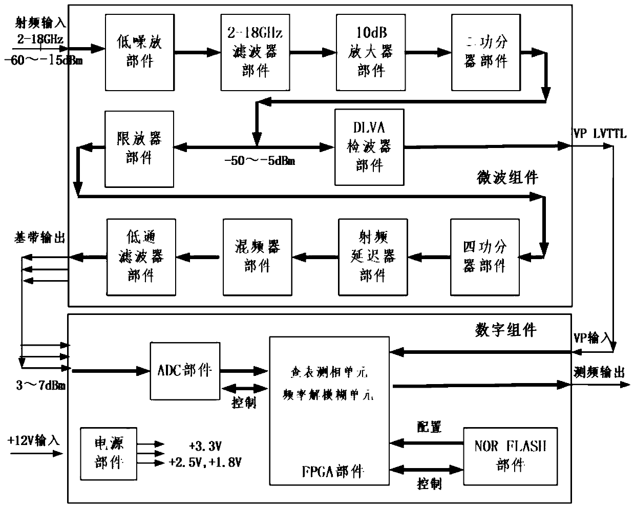
[0055] Such as figure 1 As shown, in this embodiment, an analog delay line receiver includes a low-noise amplifier component, a 2-18GHz filter component, a 10dB amplifier component, a two-power divider component, a DLVA detector component, and an amplifier limiter component, Four power splitter components, radio frequency delayer components, mixer components and low pass filter components;

[0056] The low noise amplifier component is connected to the 2-18GHz filter component;

[0057] The 2-18GHz filter part is connected to the 10dB amplifier part;

[0058] The 10dB amplifier part is connected to the two power divider parts;

[0059] The two power divider components, one of which is connected to the DLVA detector component, and the other is connected to the limiter component;

[0060] The limiter part is connected to the four-power splitter part;

[0061] The four power divider parts are connected to the radio frequency delayer part at the same time in four ways;

[006...


PUM


Abstract

The invention discloses an analog delay line receiver and an implementation method thereof. The analog delay line receiver comprises a microwave assembly and a digital assembly, wherein the microwaveassembly comprises a low-noise amplifier component, a 2-18GHz filter component, a 10dB amplifier component, a two-power divider component, a DLVA detector component, a limiter component, a four-powerdivider component, a radio frequency delayer component, a mixer component and a low-pass filter component; the digital assembly comprises a power supply part, an NOR FLASH part, an ADC part and an FPGA part. The power supply part is divided into an analog power supply module and a digital power supply module; the NOR FLASH component is connected with the power supply component and the FPGA component; the ADC part is connected with the power supply assembly and the FPGA part; and the FPGA component is connected with the ADC component and the power supply component. According to the invention, the sensitivity of the width-preserving detection VP is further optimized, the dynamic range of the input signal is increased, better quantization precision is provided for digital channelization, andthe difficulty of digital channelization in false detection of the pulse-to-pulse noise of the saturated intermediate frequency signal is solved.

Description

technical field [0001] The invention relates to a high-speed signal processing structure of an analog delay line receiver, which is widely used to guide fast frequency synthesis of electronic warfare receivers, or wideband signal reconnaissance and sorting, and belongs to the technical field of electronic warfare. Background technique [0002] At present, most types of UWB 2-18GHz instantaneous receivers are digital single-bit receivers and analog delay line receivers. The former represents the direction of digital technology, based on single-bit sampling analog-to-digital conversion devices above 40GSPS, using single-bit approximate nuclear fast Fourier transform (FFT) technology or parallel fast Fourier transform technology to achieve fast frequency measurement. The latter represents the direction of analog technology, based on delay devices such as delay lines, using techniques such as phase difference method to achieve rapid frequency measurement. [0003] A high-speed ...

Claims


Application Information

Patent Timeline
Patent Type & Authority Applications(China)
IPC IPC(8): H04B1/00H04B1/16
CPCH04B1/0007H04B1/16
Inventor 张勇强龚非吴鸿海陶琨祝俊
Owner 南京航天工业科技有限公司
Learn More