Heat dissipation device and heat dissipation method for vehicle-mounted liquid cooling system

A technology of a heat dissipation device and a heat dissipation method, which is applied in the directions of power units, electric power units, vehicle components, etc., can solve problems such as failure to work normally, loud fan noise, and increased energy consumption.

Active Publication Date: 2021-06-04
ZHUZHOU ELECTRIC LOCOMOTIVE CO LTD
View PDF0 Cites 0 Cited by
  • Summary
  • Abstract
  • Description
  • Claims
  • Application Information

AI Technical Summary

Problems solved by technology

[0003] The current vehicle-mounted liquid cooling system has the following deficiencies: a. In view of the large demand for heat dissipation, it can only be solved by increasing the power and size of the heat dissipation fan, which will cause increased energy consumption; b. In order to improve heat dissipation Efficiency, it is often necessary to increase the speed of the fan, and this will cause the noise of the fan to be loud when it is working, which is not conducive to vehicle noise control; c. It is highly dependent on the cooling fan. Once the cooling fan fails, the cooled object will be affected by the temperature. too high to work

Method used


Image

  • Heat dissipation device and heat dissipation method for vehicle-mounted liquid cooling system
  • Heat dissipation device and heat dissipation method for vehicle-mounted liquid cooling system
  • Heat dissipation device and heat dissipation method for vehicle-mounted liquid cooling system

Examples


Embodiment Construction

[0033] For ease of understanding, the present invention will be further described below in conjunction with the accompanying drawings.

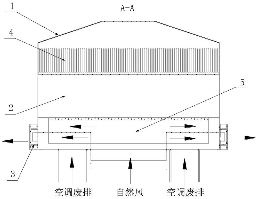
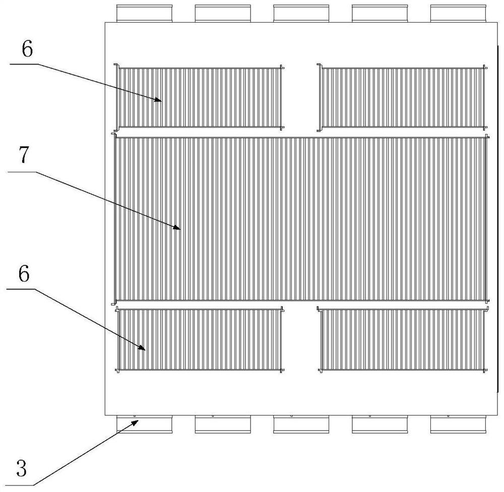
[0034] see Figure 1 ~ Figure 3 , figure 1 It is a schematic front view of a heat dissipation device for a vehicle-mounted liquid cooling system provided by an embodiment of the present invention, figure 2 yes figure 1 Schematic diagram of the section A-A in the middle, image 3 yes figure 1 bottom view.

[0035] The heat dissipation device for the vehicle-mounted liquid cooling system provided by the embodiment of the present invention includes a top cover 1, a liquid tank 2 and an air box, wherein the liquid tank 2 is used to communicate with the circulation pipeline of the cooling liquid, and the cooling in the vehicle-mounted liquid cooling system The liquid flows into the liquid tank 2 after passing through the object to be cooled (such as a battery reactor, etc.), and flows back to the object to be cooled after the temperature of ...


PUM


Abstract

The invention provides a heat dissipation device and a heat dissipation method for a vehicle-mounted liquid cooling system. The heat dissipation device comprises a liquid tank (2), a top cover (1) covering the upper surface of the liquid tank, and a bellows located below the liquid tank. The liquid tank is used to communicate with the circulation pipeline of the cooling liquid. The top cover and the upper surface of the liquid tank together form a traveling air channel for the traveling air of the vehicle to pass through. A plurality of first heat dissipation plates parallel to each other are arranged along the extending direction of the running air channel. The bellows is provided with a plurality of mutually parallel second radiating plates connected to the lower surface of the liquid tank, the second radiating plates are arranged in a direction perpendicular to the first radiating plates, the air inlet of the bellows is located on the bottom surface, and the air outlet is located in the A fan (3) is arranged at the air outlet on the side corresponding to the end of the heat dissipation plate. Using the heat dissipation device provided by the invention can reduce the degree of dependence on the heat dissipation fan, help reduce energy consumption and avoid excessive noise of the fan.

Description

technical field [0001] The invention relates to the technical field of vehicle cooling systems, in particular to a heat dissipation device and a heat dissipation method for a vehicle liquid cooling system. Background technique [0002] Some high-power devices on vehicles, such as on-board energy storage devices (lithium batteries or fuel cells), traction motors, etc., will generate a lot of heat during work, and most of them are cooled by liquid cooling. In the current vehicle-mounted liquid cooling system, the coolant flows through the object to be cooled and then flows into the cooling water tank, while the cooling fan forces air to cool the cooling water tank to dissipate heat, and then the coolant in the cooling water tank flows back to the object to be cooled, so , through the circulating flow of cooling liquid to dissipate heat for the object to be cooled. [0003] The current vehicle-mounted liquid cooling system has the following deficiencies: a. In view of the larg...

Claims


Application Information

Patent Timeline
Patent Type & Authority Patents(China)
IPC IPC(8): B60K1/00
CPCB60K1/00B60K2001/005B60K2001/006
Inventor 张伟先付鹏文午柯建明李玉梅胡润文张婷婷付亚娥唐艳丽汪培帧
Owner ZHUZHOU ELECTRIC LOCOMOTIVE CO LTD
Why Eureka
Try Eureka