
Electric firing device

A firing device and electromagnetic device technology, applied in the direction of nailing U-shaped nail tools, nailing tools, manufacturing tools, etc., can solve the problems of high overall structure height, speaker noise, and large volume, so as to reduce the structure volume and reduce operating noise , Ease of use

Inactive Publication Date: 2020-05-08
APEX MFG
View PDF8 Cites 0 Cited by
  • Summary
  • Abstract
  • Description
  • Claims
  • Application Information

AI Technical Summary

Problems solved by technology

[0003] However, in the general electromagnetically driven percussion device mentioned above, the moving direction of the driving rod and the nailing part is in the same direction as the direction of the magnetic field, which will cause the height of the overall structure to be too high and waste too much space. To have a better effect of driving out the needle, the electric firing device is relatively bulky, which is likely to cause a loudspeaker effect and make a lot of noise, and the large size will also make it difficult for workers to handle and store. Waiting for shortcomings that need to be improved

Method used


Image

  • Electric firing device
  • Electric firing device
  • Electric firing device

Examples


Embodiment Construction

[0015] The following examples illustrate possible implementations of the present invention, but they are not intended to limit the protection scope of the present invention and are stated in advance.

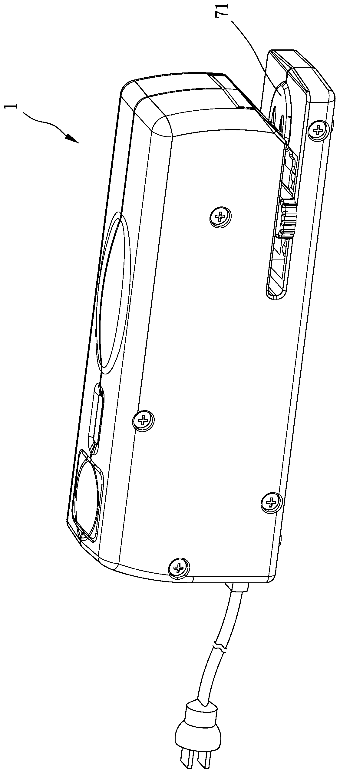
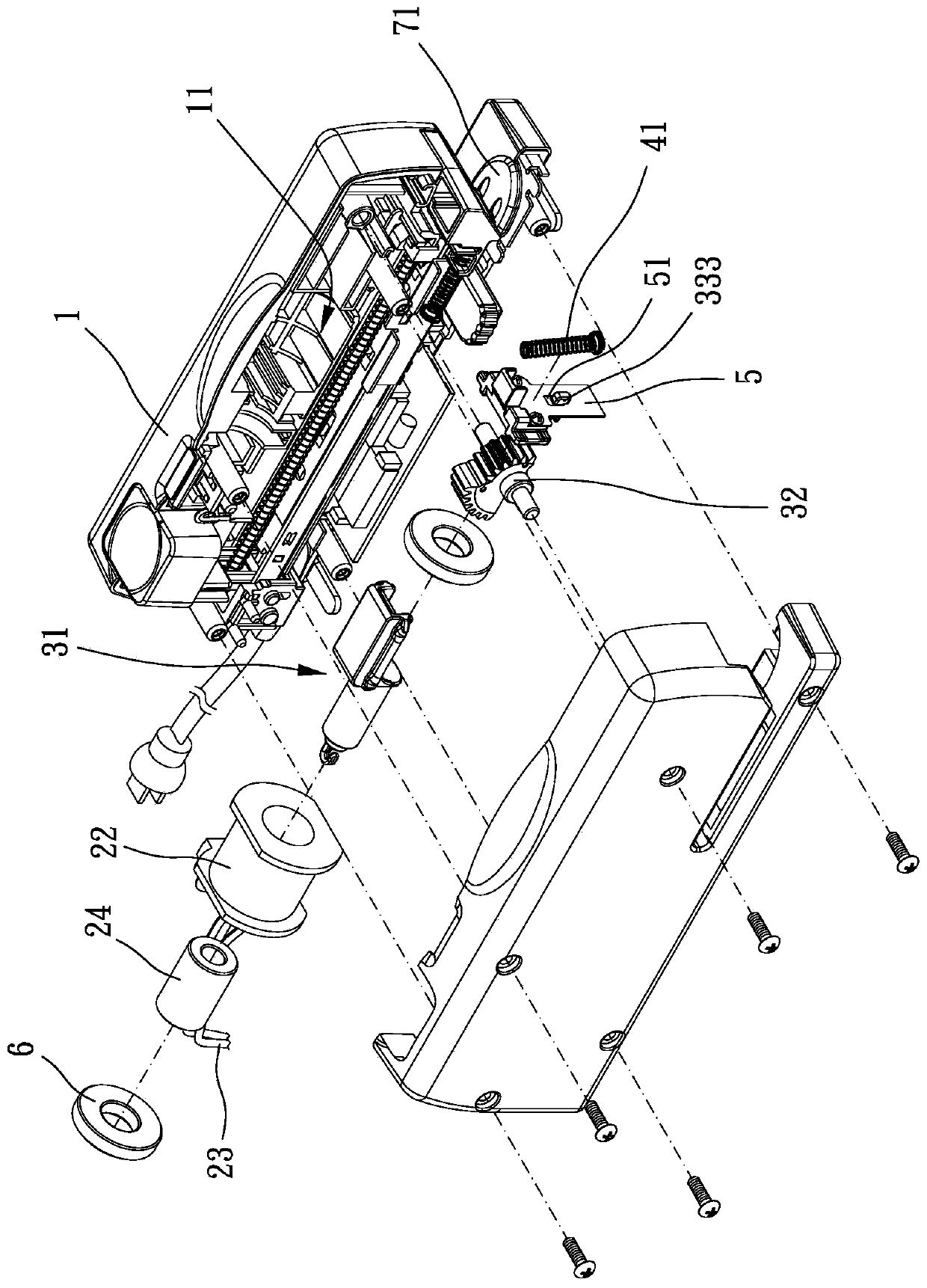
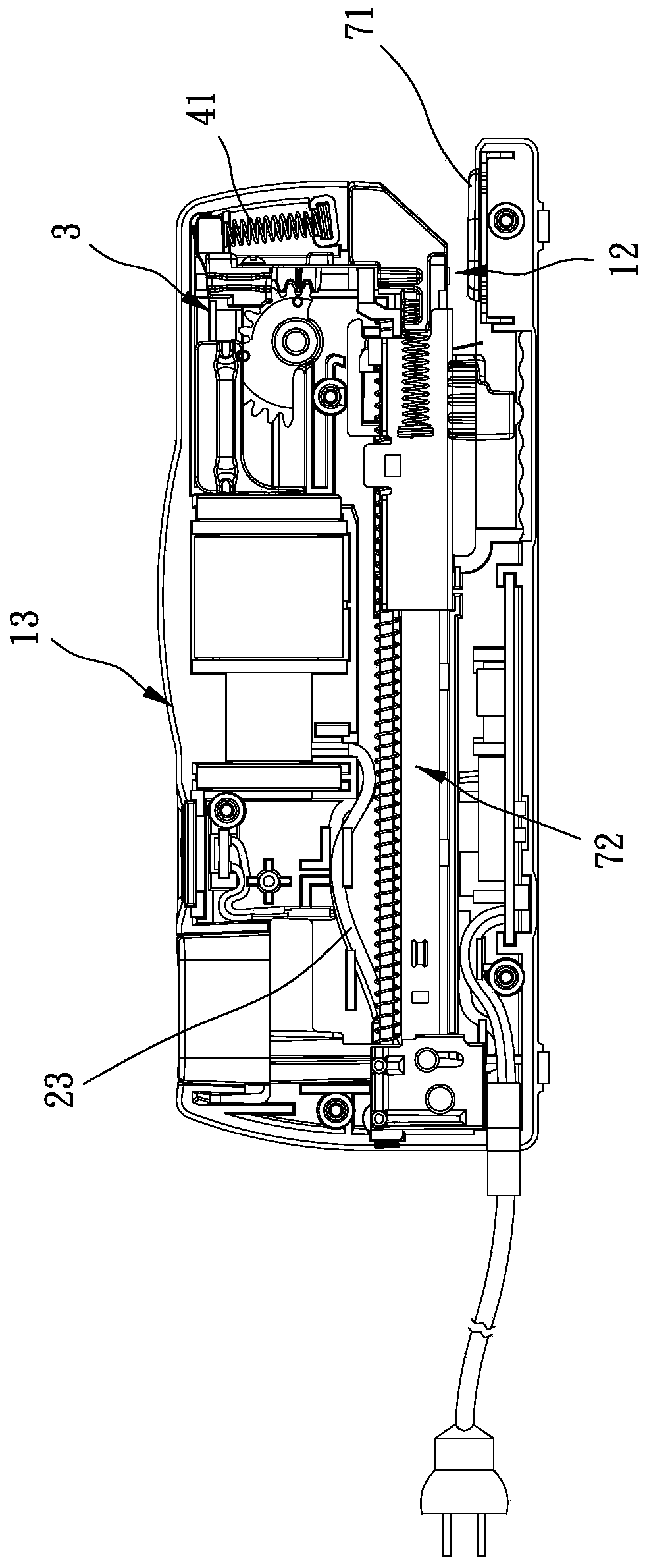
[0016] Please refer to Figure 1 to Figure 6 , which shows a first embodiment of the present invention, the electric firing device of the present invention includes a body 1 and a firing unit 2 .

[0017] The main body 1 includes an inner space 11 and a firing port 12 . The firing unit 2 is located in the internal space 11, and the firing unit 2 includes an electromagnetic device 21, a driving member 24, a steering mechanism 3 and a striking member 5, and the electromagnetic device 21 can generate magnetic force to drive The driving member 24 moves along the opening direction transverse to the firing port 12, that is, the direction of the magnetic field generated by the electromagnetic device 21 is transverse to the opening direction of the firing port 12, and the impact member...


PUM


Abstract

The invention provides an electric firing device. The electric firing device comprises a body and a firing unit. The body comprises an internal space and a firing port. The firing unit is arranged inthe internal space. The firing unit comprises an electromagnetic device, a driving part and a striking part. The electromagnetic device drives the driving part to move in the direction perpendicular to an opening of the firing port and then drive the striking part to move in the direction of the opening of the firing port. The overall structure size of the electric firing device is effectively reduced, operating noise is substantially reduced, and the electric firing device is convenient to use, carry and store by a user.

Description

technical field [0001] The invention relates to a firing device, in particular to an electric firing device. Background technique [0002] Firing devices such as staplers and staplers are often used to staple and connect different objects into one. They are widely favored by workers because of their easy operation and fast operation process. In order to meet the different work needs of workers, scientific researchers often improve its structure, such as but not limited to, improving the labor-saving mechanism, improving the capacity of the nail box, improving the firing mechanism or improving different driving methods (electric, pneumatic and manual) etc. [0003] However, in the general electromagnetically driven percussion device mentioned above, the moving direction of the driving rod and the nailing part is in the same direction as the direction of the magnetic field, which will cause the height of the overall structure to be too high and waste too much space. To have ...

Claims


Application Information

Patent Timeline
Patent Type & Authority Applications(China)
IPC IPC(8): B25C1/06B25C5/15
CPCB25C1/06B25C5/15
Inventor 胡志玮王景立
Owner APEX MFG
Learn More