


Quick Research
Generate reliable direction feasibility study reports for your R&D in just a few steps.

Technical Q&A
Discover and master advanced knowledge NOW. Basics, ideas, possibilities, all at once.

Find Solutions
As an expert in R&D theories, this can generate solutions to your technical problems instantly.

Evaluate Feasibility
Analyze your overall solution with one click, know your potential R&D risks in advance.

Monitor Landscape
Get weekly tech updates, stay abreast of the latest tech innovations and key insights.
Power supply power-on module
A technology of electrical modules and power supplies, applied in logic circuits, electrical components, logic circuit interface devices, etc., can solve problems such as leakage, redundant power consumption, and wasted power consumption that cannot be completely solved, so as to avoid circuit structure design and reduce power consumption , the effect of simple structure
- Summary
- Abstract
- Description
- Claims
- Application Information
AI Technical Summary
Problems solved by technology
Method used
Image

Examples
Embodiment 1
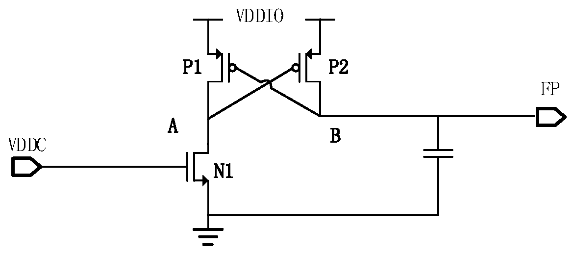
[0033] As attached image 3 As shown, a power supply module provided in this embodiment includes a VDDC power supply, a VDDIO power supply, a pull-down NMOS tube N1, a first transmission PMOS tube P1, a second transmission PMOS tube P2, and a delay unit. The delay unit is specifically The first capacitor; where the gate of the pull-down NMOS tube N1 is connected to the VDDC power supply, the drain of the pull-down NMOS tube N1 is grounded, the source is connected to the A node, and the sources of the first transmission PMOS tube P1 and the second transmission PMOS tube P2 are simultaneously connected VDDIO power supply, the drain is connected to node A and node B, the gate is connected to node B and node A, and node A and node B are mutually opposite signals. One end of the first capacitor is grounded, and the other end is connected to node B. In this embodiment, the first capacitor only plays a role of delay, so multiple types of capacitors can be used, including but not limite...
Embodiment 2
[0037] As attached Figure 4 As shown, compared with Embodiment 1, the power-on module provided by this embodiment adds a feedback unit. The feedback unit includes a feedback MOS transistor N2. The source of the feedback MOS transistor N2 is grounded, the drain is connected to node B, and the gate is Connect to node A. Once the feedback unit detects the potential difference between the A node and the B node, and the potential difference reaches the turn-on voltage of the feedback MOS transistor N2, the feedback MOS transistor N2 is turned on, which can further reduce the voltage of the B node, so that the B node The voltage drops quickly to a low level, that is, grounded. The rest of the circuit structure is the same as the first embodiment.
[0038] Please continue to refer to the attached Figure 4 When the VDDIO power supply is powered on and the VDDC power supply is not powered on, the pull-down NMOS transistor N1 is in the off state, and the first capacitor in the charged s...
Embodiment 3
[0041] As attached Figure 5 As shown, a power supply module provided in this embodiment includes a VDDC power supply, a VDDIO power supply, a pull-down NMOS tube N1, a first transmission PMOS tube P1, a second transmission PMOS tube P2, and a delay unit. The delay unit is specifically The second capacitor; where the gate of the pull-down NMOS transistor N1 is connected to the VDDC power supply, the drain of the pull-down NMOS transistor N1 is grounded, the source is connected to the A node, and the sources of the first transmission PMOS transistor P1 and the second transmission PMOS transistor P2 are simultaneously connected VDDIO power supply, the drain is connected to node A and node B, the gate is connected to node B and node A, and node A and node B are mutually opposite signals. One end of the second capacitor is connected to the source of the first transmission MOS transistor P1, and the other end is connected to the drain of the first transmission MOS transistor P1, and ...
PUM
 Abstract
Description
Claims
Application Information
 - R&D Engineer
- R&D Manager
- IP Professional
- Industry Leading Data Capabilities
- Powerful AI technology
- Patent DNA Extraction
Browse by: Latest US Patents, China's latest patents, Technical Efficacy Thesaurus, Application Domain, Technology Topic, Popular Technical Reports.
© 2024 PatSnap. All rights reserved.Legal|Privacy policy|Modern Slavery Act Transparency Statement|Sitemap|About US| Contact US: help@patsnap.com