
A kind of ultraviolet led packaging structure

A technology of LED packaging and LED chips, applied in semiconductor devices, electrical components, circuits, etc., can solve problems such as poor reliability, achieve the effects of reducing exposure, reducing the risk of leakage, and preventing the migration of metal atoms

Active Publication Date: 2021-07-02
QUANZHOU SANAN SEMICON TECH CO LTD
View PDF8 Cites 0 Cited by
  • Summary
  • Abstract
  • Description
  • Claims
  • Application Information

AI Technical Summary

Problems solved by technology

[0008] The present invention aims to provide an ultraviolet LED packaging structure to solve the problem of poor reliability of the existing ultraviolet LED packaging structure

Method used


Image

  • A kind of ultraviolet led packaging structure
  • A kind of ultraviolet led packaging structure
  • A kind of ultraviolet led packaging structure

Examples


Embodiment 1

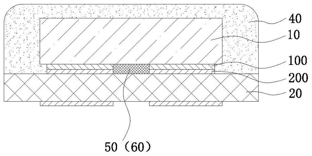
[0038] Such as image 3 As shown, this embodiment provides an ultraviolet LED packaging structure, which includes an ultraviolet LED chip 10 in a flip-chip structure, a packaging substrate 20 and an encapsulating adhesive 40 covering the ultraviolet LED chip 10 . The wavelength of the LED chip 10 can be between 200-380nm, and the light-emitting wavelength can be selected according to the needs of practical applications, such as surface sterilization and surface curing. Preferably, the LED chip 10 is 200-340nm.

[0039] Wherein, the ultraviolet LED chip 10 is a flip-chip structure, and there are two chip electrodes 100 as positive and negative electrodes on the bottom surface away from the light-emitting surface. The packaging substrate 20 can be ceramic materials such as aluminum nitride and aluminum oxide, preferably aluminum nitride ceramic materials with a larger thermal conductivity. The packaging substrate 20 has at least two substrate electrodes 200 matched with the chi...

Embodiment 2

[0051] Such as Figure 7 and Figure 8 As shown, this embodiment also provides an ultraviolet LED packaging structure, which is roughly the same as the ultraviolet LED packaging structure in Embodiment 1, the difference is that the packaging glue of the ultraviolet LED packaging structure in this embodiment The packaging methods of the material 40 are different.

[0052] The packaging adhesive 40 of the ultraviolet LED packaging structure in this embodiment is completely coated on the surface of the package along the surface of the chip and the surface of the ceramic substrate by vacuum filming. Since the surface of the ceramic substrate in contact with the fluororesin itself has metal bumps, And inherent LED chips or other components, the surface is uneven, so the packaging structure after vacuum coating forms a concave-convex curved surface structure. The thickness of the fluororesin film of this structure should be smaller than that of the LED chip, preferably, the film t...


PUM

PropertyMeasurementUnit
thicknessaaaaaaaaaa
emission peakaaaaaaaaaa
crystallinityaaaaaaaaaa

Abstract

The invention relates to an ultraviolet LED packaging structure, which includes an ultraviolet LED chip with a flip-chip structure, a packaging substrate with at least two substrate electrodes, and a packaging adhesive covering the ultraviolet LED chip. The positive and negative chip electrodes of the ultraviolet LED chip are respectively connected to the The two substrate electrodes are connected, and there is an insulating gap between the positive and negative chip electrodes and the two substrate electrodes. The insulating gap is filled with a shield, the shield is a fluororesin material containing some crystals, to solve the problem of existing ultraviolet rays. The problem of poor reliability of LED packaging structure.

Description

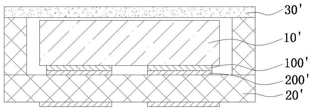
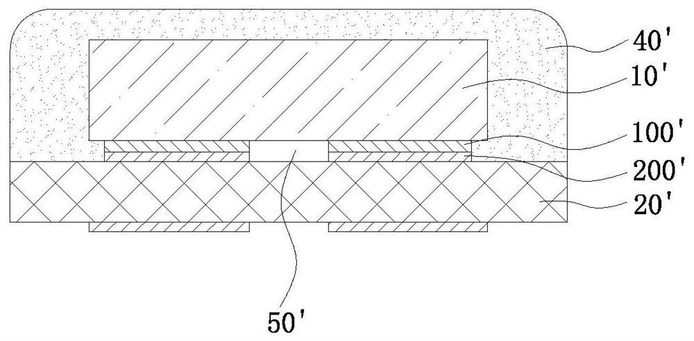
technical field [0001] The invention relates to the field of LED packaging, in particular to an ultraviolet LED packaging structure. Background technique [0002] Most of the existing ultraviolet LED packaging adopts flip-chip LED chips, and the common packaging structure is glass packaging with high ultraviolet transmittance, or resin material packaging that is resistant to ultraviolet radiation. glass package (such as figure 1 Shown) is to fix the UV LED chip 10' of the flip-chip structure in the bowl cup of the package substrate 20' by means of solder paste or eutectic soldering, and make the chip electrode 100' of the UV LED chip 10' and the bowl cup The inner substrate electrode 200' is bonded and fixed, and then a quartz glass plate 30' is fixed at the opening of the bowl, so that a closed chamber is formed inside the bowl. [0003] Resin material encapsulation (such as figure 2 shown) is to solidify the UV LED chip 10' on the packaging substrate 20' by means of so...

Claims


Application Information

Patent Timeline
Patent Type & Authority Patents(China)
IPC IPC(8): H01L33/48H01L33/52H01L33/56H01L33/62
CPCH01L33/48H01L33/62H01L33/52H01L33/56
Inventor 黄森鹏陈顺意黄永特余长治徐宸科
Owner QUANZHOU SANAN SEMICON TECH CO LTD
Learn More