
BiLSTM-based composite characteristic optical fiber sensing disturbance signal mode identification method

A perturbation signal, optical fiber sensing technology, applied in the recognition of patterns in signals, character and pattern recognition, and the use of optical devices to transmit sensing components. It can solve the problems of insufficient theoretical basis, inability to extract waveform transformation, and low efficiency. , to achieve the effect of improving the recognition rate, strong universality and portability, and rapid recognition and classification

Active Publication Date: 2020-05-05
TIANJIN UNIV
View PDF6 Cites 5 Cited by
  • Summary
  • Abstract
  • Description
  • Claims
  • Application Information

AI Technical Summary

Problems solved by technology

The traditional methods of signal recognition mainly include short-term average zero-crossing rate ZC based on time-domain characteristics, differential short-term average zero-crossing DZC, short-term average energy E, differential short-term average energy DE, and disturbance duration. Analysis of time-amplitude information can characterize some local features of the signal, but cannot extract useful information such as waveform transformation; there is a wavelet packet decomposition method based on frequency domain feature analysis, which decomposes the signal into sub-frequency bands to extract energy features, extract features Vector can solve the problem of non-stationary signals; the method based on empirical mode decomposition EMD has insufficient theoretical basis and requires multiple iterative calculations, which is not efficient

Method used


Image

  • BiLSTM-based composite characteristic optical fiber sensing disturbance signal mode identification method
  • BiLSTM-based composite characteristic optical fiber sensing disturbance signal mode identification method
  • BiLSTM-based composite characteristic optical fiber sensing disturbance signal mode identification method

Examples


Embodiment Construction

[0019] The technical solutions of the present invention will be further elaborated below in conjunction with specific implementation examples and accompanying drawings.

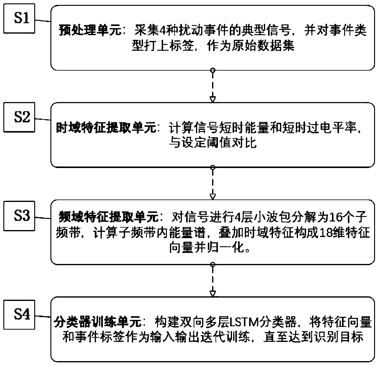
[0020] figure 1 It is a schematic flow chart of the composite feature optical fiber signal recognition method based on the LSTM algorithm provided by the present invention, a fiber sensing disturbance signal recognition method using time-frequency domain composite features, including four units: a preprocessing unit, a time domain feature extraction unit, Frequency domain feature extraction unit, classifier training unit.

[0021] The Distributed Optical Fiber Sensing System disturbance signal recognition method based on the BiLSTM algorithm designed by the present invention is characterized in that comprising the following steps:

[0022] S1: collect the vibration signal in the optical fiber and store the signal data, and add the type label;

[0023] These include building a distributed optical fiber sensi...


PUM


Abstract

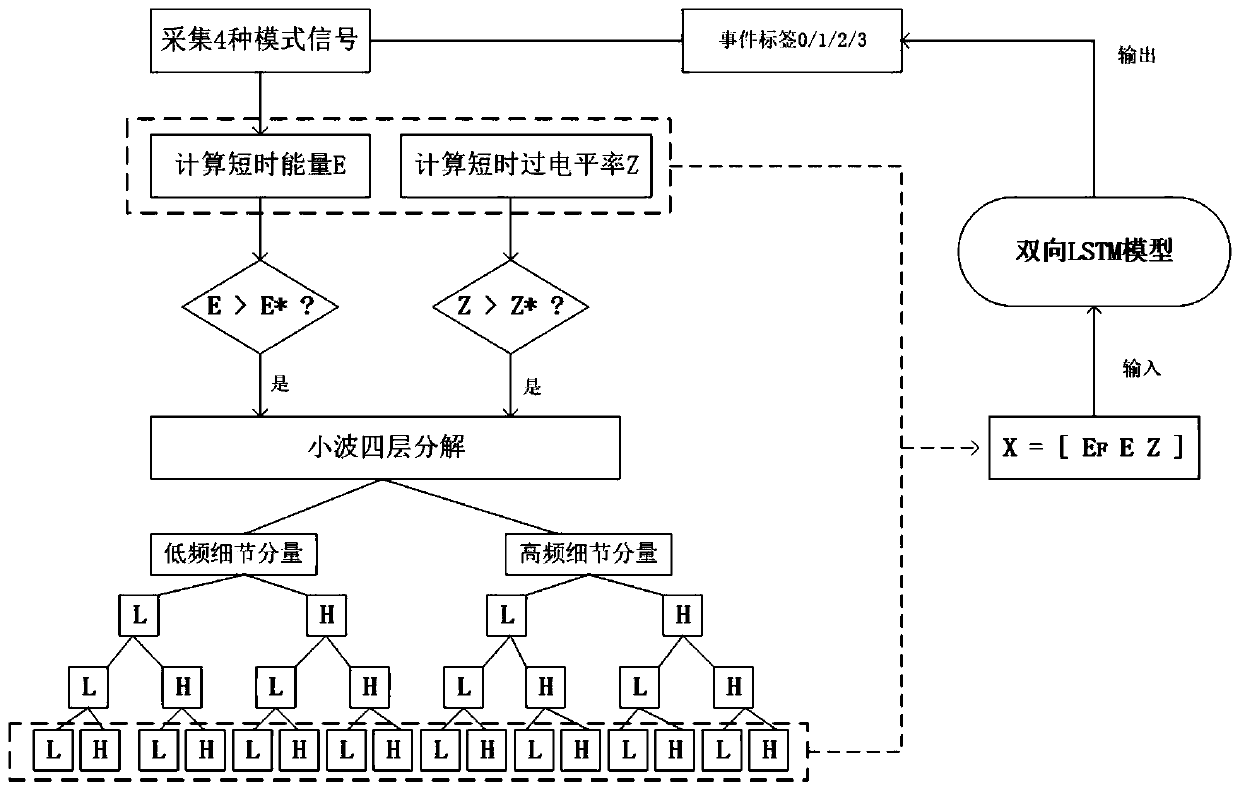
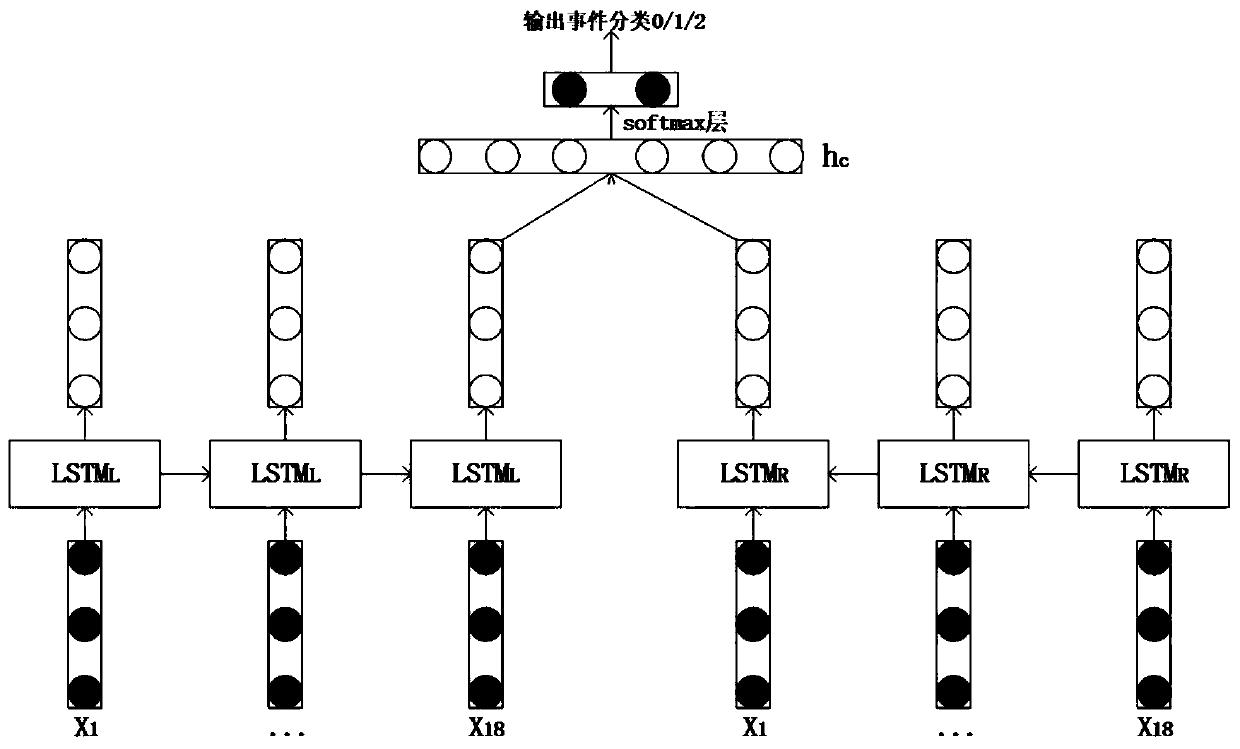
The invention relates to a BiLSTM-based composite characteristic optical fiber sensing disturbance signal mode identification method, which comprises the following steps that vibration signals including optical fiber sensing disturbance signals in different modes are collected, data is stored, and type labels are added; the time domain feature extraction unit is used for calculating short-time energy and a short-time over-level rate for the acquired vibration signals, setting thresholds of the short-time energy and the short-time over-level rate, and preliminarily judging intrusion disturbancesignals according to judgment conditions; the frequency domain feature extraction unit is used for carrying out four-layer wavelet packet decomposition on each vibration signal, solving 16 sub-band energy spectrum distribution, splicing short-time energy and short-time over-level rate to form a composite feature vector, carrying out normalization processing on the composite feature vector, and taking the normalized feature vector as an input feature vector; and a bidirectional LSTM network model is constrcuted, the normalized feature vector is taken as an input, the event label is taken as aclassification output result, and a classifier is trained by using the test sample to realize optical fiber sensing disturbance signal mode identification.

Description

technical field [0001] The invention relates to the field of optical fiber sensing signal identification, in particular to a method for classifying and identifying events of optical fiber sensing disturbance signals based on the BiLSTM algorithm. Background technique [0002] The distributed optical fiber sensing system has the advantages of high sensitivity, simple structure, long detection distance, less susceptible to interference, and no power supply. It has been widely used in peripheral security, oil and gas pipeline detection and other fields. In the field of perimeter security, the optical fiber sensing system uses optical fiber as the sensing element, which can be wound on the fence or buried in the ground. By collecting the sensing signal, the signal processing and analysis module is used to classify and identify the disturbance signal. The purpose of identifying the type of vibration intrusion signal is achieved. At present, the typical optical fiber perimeter pr...

Claims


Application Information

Patent Timeline
IPC IPC(8): G06K9/00G06N3/04G06N3/08G01D5/353
CPCG06N3/08G01D5/353G06N3/044G06N3/045G06F2218/02G06F2218/08G06F2218/12
Inventor 吕辰刚樊丽会
Owner TIANJIN UNIV
Learn More