
Household garbage gasification treatment system with composite dechlorination function

A domestic waste and treatment system technology, which is applied in the field of compound dechlorination domestic waste gasification treatment system, can solve the problems of equipment high-temperature corrosion, high-temperature corrosion, low power generation rate, etc., and achieve the effect of reasonable structure

Pending Publication Date: 2020-05-01
ZHEJIANG UNIVERSITY OF SCIENCE AND TECHNOLOGY +1
View PDF0 Cites 0 Cited by
  • Summary
  • Abstract
  • Description
  • Claims
  • Application Information

AI Technical Summary

Problems solved by technology

[0004] The present invention mainly solves the problem in the prior art that HCl can only be removed through a low-temperature tail gas purification device, which easily causes high-temperature corrosion of equipment, thereby limiting the steam parameters of waste incineration power generation, resulting in low power generation rate, and is easy to directly Or indirectly cause technical problems such as dioxin formation, etc., provide a direct deep dechlorination of combustible gas after the gasifier generates combustible gas, avoid high-temperature corrosion of subsequent equipment by combustible gas, thereby improving steam parameters and improving power generation efficiency, And help to reduce dioxins in the process of flue gas cooling, low-temperature heterogeneous catalytic synthesis of composite dechlorination domestic waste gasification treatment system

Method used


Image

  • Household garbage gasification treatment system with composite dechlorination function
  • Household garbage gasification treatment system with composite dechlorination function
  • Household garbage gasification treatment system with composite dechlorination function

Examples


Embodiment 1

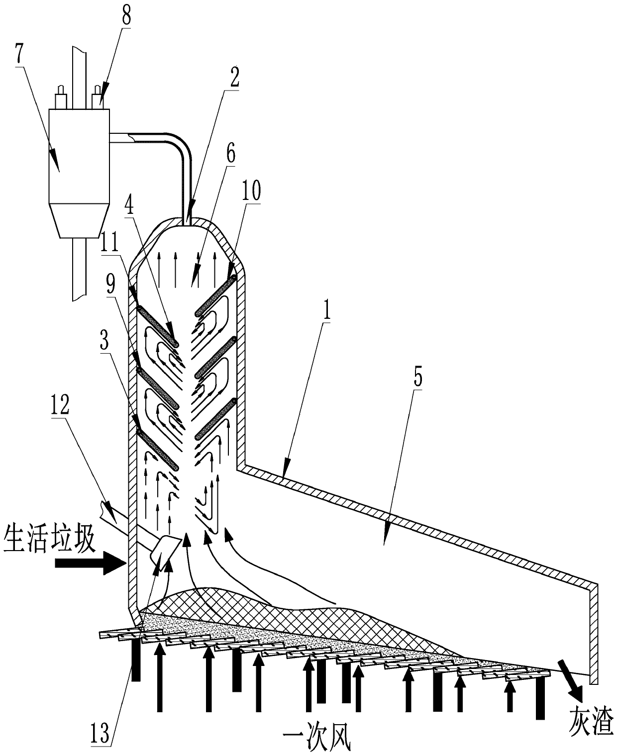
[0029] according to figure 1 A compound dechlorination domestic waste gasification treatment system shown includes a gasifier 1 and a compound dechlorination system, and is characterized in that the compound dechlorination system includes a chlorine coarse filter device and a cyclone separator 7 for dechlorination device, the chlorine coarse filtration device includes a plurality of filter plates arranged from top to bottom in the gasification furnace 1 and a calcium injection port 2 on the gasification furnace 1, and the One end of the filter plate is connected to the gasification furnace 1, and the filter plate is inclined downward from the fixed end 3 to the free end 4. The gasification furnace 1 includes a gasification reaction layer 5 and is used to place the The filter layer 6 of the chlorine coarse filter device, the filter layer 6 is arranged on the top of the gasification reaction layer 5, and the calcium injection port 2 is arranged at the gasification reaction layer...

Embodiment 2

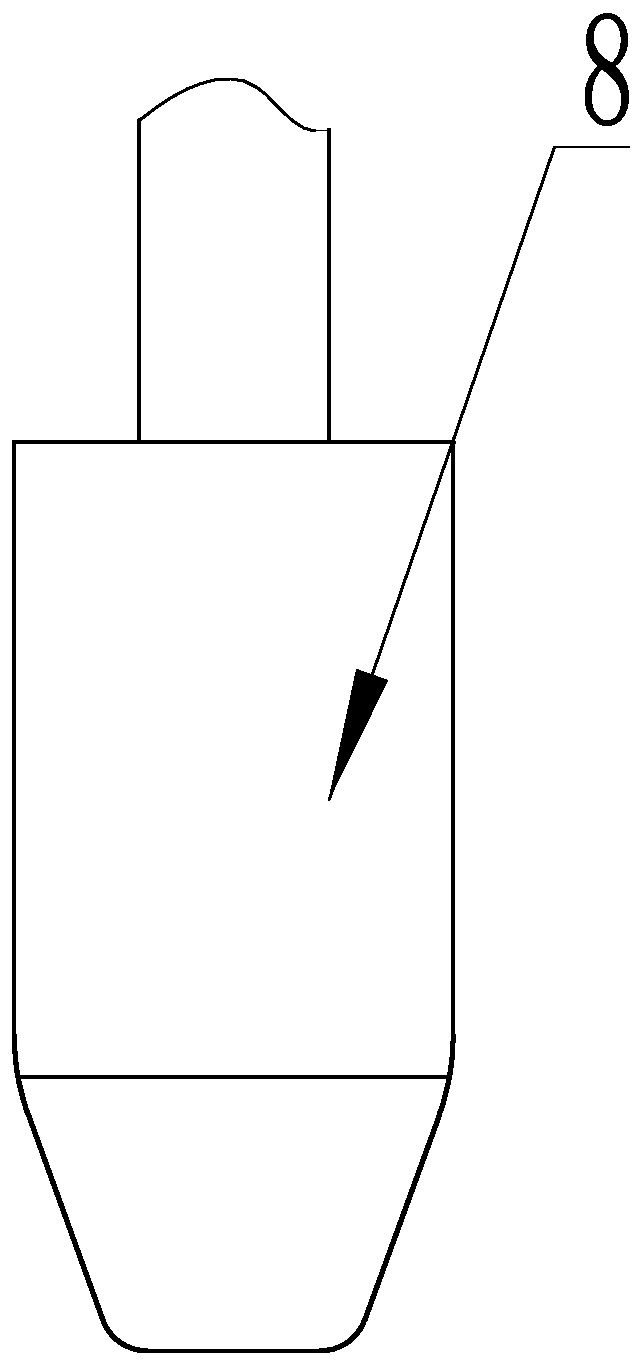
[0032] according to figure 1 and image 3 As shown, the difference between this embodiment and Embodiment 1 is that the cyclone separator 7 dechlorination device includes a cyclone separator 7 connected to the gas outlet of the gasifier 1, and the cyclone separator The top of 7 is provided with several dechlorinating agent nozzles 8, and the dechlorinating agent nozzles 8 are connected with the first dechlorinating agent chamber through the first air blower.

[0033] Compared with Example 1, this embodiment further limits the dechlorination device of the cyclone separator 7, and the function of combining the fine filtration of chlorine with the cyclone separator 7 arranged outside the gasifier 1 is to avoid intracranial high temperature Removal of chlorine, so as to realize the medium and high temperature dechlorination of crude gasification gas (medium and high temperature dechlorination technology refers to the use of solid-phase dechlorination agent to absorb HCl gas in cr...

Embodiment 3

[0035] according to Figure 1 to Figure 2 As shown, the difference between this embodiment and Embodiment 1 is that the filter plate includes the left filter plate 9 located on the left side of the gasifier 1 and the filter plate 9 located on the right side of the gasifier 1 The right filter plate 10 described above, the left filter plate 9 and the right filter plate 10 are arranged alternately from top to bottom in the gasification furnace 1 to form a bow-shaped baffle area, and the upper and lower two are adjacent The left filter plate 9 and the right filter plate 10 form a single filter cycle, and the gasifier 1 is provided with several filter cycles.

[0036] Compared with Embodiment 1, this embodiment further defines the filter plate, which includes the left filter plate 9 located on the left side of the gasifier 1 and the right filter plate located on the right side of the gasifier 1 10. The left filter plate 9 and the right filter plate 10 are arranged alternately from...


PUM


Abstract

The invention relates to a household garbage gasification treatment system with a composite dechlorination function. The system comprises a gasification furnace and a composite dechlorination system,wherein the composite dechlorination system comprises a coarse chlorine filtration device and a cyclone separator dechlorination device, the coarse chlorine filtration device comprises a plurality offiltering plates arranged in the gasification furnace from top to bottom and a calcium spraying port formed in the gasification furnace, one end of the filtering plate is connected with the gasification furnace, the filtering plate inclines downwards from the fixed end to the free end, the gasification furnace comprises a gasification reaction layer and a filter layer for placing the coarse chlorine filtration device, the filter layer is arranged at the top of the gasification reaction layer, and the calcium spraying port is arranged at the gasification reaction layer. According to the invention, after combustible gas is generated in a gasification furnace, the combustible gas can be directly subjected to deep dechlorination, so that high-temperature corrosion of the combustible gas to subsequent equipment is avoided so as to improve the steam parameters and the power generation efficiency and easily reduce the low-temperature heterogeneous catalytic synthesis of dioxin in the flue gascooling process.

Description

technical field [0001] The invention relates to a domestic garbage gasification treatment system, in particular to a composite dechlorination domestic garbage gasification treatment system. Background technique [0002] The treatment and disposal of domestic garbage and other wastes is a major problem that needs to be solved urgently in our country. Among them, the incineration power generation technology has the advantages of high degree of harmlessness, significant effect of volume and weight reduction, and energy recovery and utilization. It has been developed and applied relatively rapidly in recent years. However, the incineration process of domestic waste will inevitably produce secondary pollutants, especially chlorine-containing pollutants such as dioxin and hydrogen chloride (HCl), which will cause great harm to the environment and human health. On the one hand, the chlorine contained in domestic waste mainly forms HCl after incineration, and its content in waste in...

Claims


Application Information

Patent Timeline
IPC IPC(8): C10J3/48C10J3/82C10J3/84
CPCC10J3/48C10J3/82C10J3/84
Inventor 汤元君董隽李国能郑友取
Owner ZHEJIANG UNIVERSITY OF SCIENCE AND TECHNOLOGY
Learn More