A residual gas charged particle beam monitoring device and method thereof

A technology of charged particle beams and monitoring devices, applied in measuring devices, radiation measurement, X/γ/cosmic radiation measurement, etc., can solve the problems of cumbersome operation, poor time resolution, cost increase, etc., and achieve high measurement efficiency and good The effect of position resolution and simple structure

Active Publication Date: 2022-02-18
INST OF MODERN PHYSICS CHINESE ACADEMY OF SCI
View PDF0 Cites 0 Cited by
  • Summary
  • Abstract
  • Description
  • Claims
  • Application Information

AI Technical Summary

Problems solved by technology

Depending on the performance of the optical system and CCD camera, the enhanced CCD camera detector can achieve a better position resolution of 100 μm or even tens of μm; but its image acquisition frequency is about 100Hz, and the time resolution is very poor, about 10ms
In order to solve the problem of poor time resolution of the enhanced CCD camera detector, it is generally necessary to configure other detector types for time measurement, resulting in complex structure, higher cost and more cumbersome operation of RGIPM
In addition, CCD cameras do not have the property of anti-radiation, so they cannot be used in scenes with strong radiation environment
A detection technology that is similar to CCD cameras and has radiation resistance is the Charge Injection Device (CID) camera, but it has no advantages over CCD cameras in many other properties, such as its low quantum efficiency, narrow corresponding range, Low signal-to-noise ratio, large dark current, etc.
In short, although the MCP detector based on CCD or CID camera technology can achieve high position resolution, it cannot have good time resolution at the same time.

Method used


Image

  • A residual gas charged particle beam monitoring device and method thereof
  • A residual gas charged particle beam monitoring device and method thereof
  • A residual gas charged particle beam monitoring device and method thereof

Examples


Embodiment Construction

[0046] In the description of the present invention, it should be understood that the orientation or positional relationship indicated by the terms "upper", "lower", "inner", "outer" and so on is based on the orientation or positional relationship shown in the drawings, and is only for convenience The present invention is described and simplified descriptions do not indicate or imply that the device or element referred to must have a specific orientation, be constructed and operate in a specific orientation, and thus should not be construed as limiting the present invention. The present invention will be described in detail below in conjunction with the accompanying drawings and embodiments.

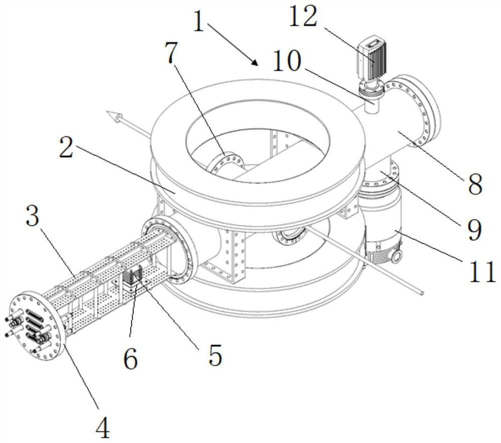
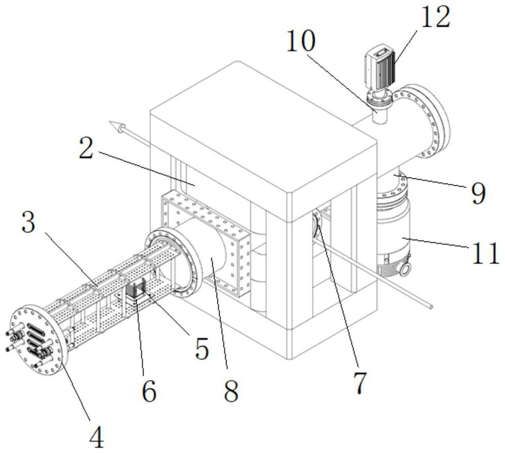
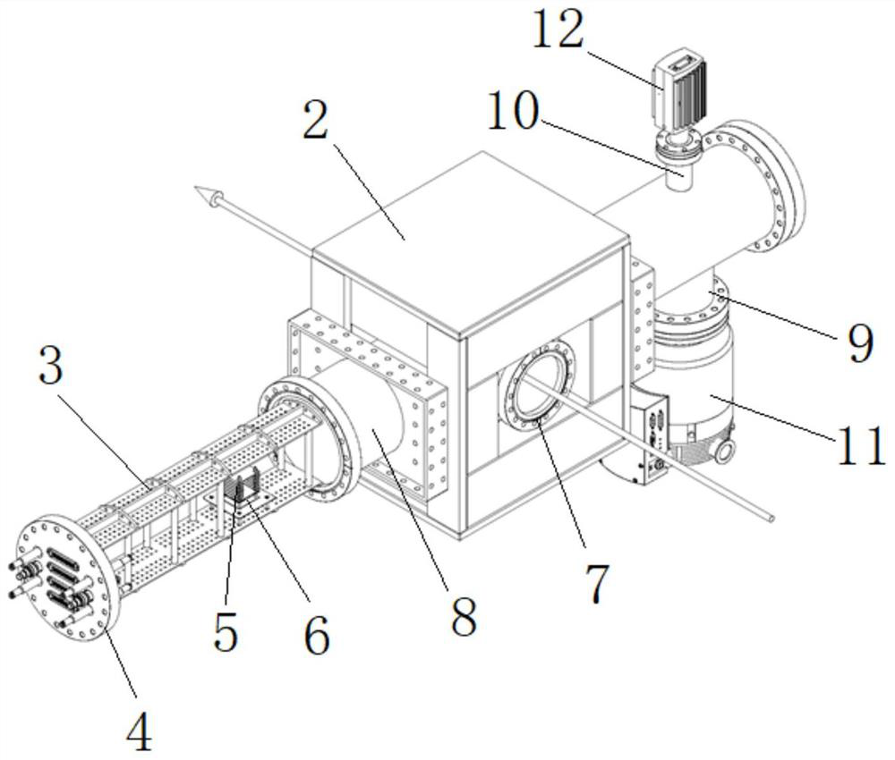
[0047] Such as Figure 1 ~ Figure 3 As shown, the present invention provides a residual gas charged particle beam monitoring device, which realizes high-precision full-function beam density monitoring based on MCP and charge-collecting pixel chip technology. The device of the present inv...


PUM


Abstract

The invention relates to a residual gas charged particle beam monitoring device and method thereof, which comprises an ultra-high vacuum chamber, a magnet is arranged outside the ultra-high vacuum chamber, the ultra-high vacuum chamber is connected to a support, and the support is connected to a lead flange; an electric field device and a high-precision two-dimensional position-sensitive detector are set on the bracket; the bottom of the detector is provided with a pixel chip binding plate, and the charge-collecting pixel detector is located at the center of the pixel chip binding plate, and the chip on the pixel chip binding plate The peripheral circuit is connected, and the chip peripheral circuit on the pixel chip binding board is connected to the external data acquisition system through the external interface; the anode electronic adjustment electrode, MCP, MCP power supply electrode and secondary electron are fixedly arranged on the top of the pixel chip binding board in sequence Inhibition electrode. The invention can measure the density distribution, direction, intensity and time structure of the charged particle beam in a non-intercepting manner in real time in an ultra-high vacuum environment, and can be widely used in various proton accelerators and heavy ion accelerators.

Description

technical field [0001] The invention relates to the field of beam current measurement of charged particle beams, in particular to a residual gas charged particle beam current monitoring device and method thereof. Background technique [0002] Particle accelerator is an important basic scientific research facility for human beings to understand the microstructure of matter. In accelerator experiments and applications, efficient and stable beam distribution is the primary factor for the success of experiments, and beam monitoring technology in beam adjustment is a key part of improving beam adjustment efficiency and beam quality. There are two main types of beam monitoring technologies, namely, intercepting beam detection and non-intercepting beam detection. [0003] Interception beam detection technology includes fluorescent screen detectors, Faraday cage array detectors, single-filament or multi-filament scanning detectors and MCP detectors. Among them, the fluorescent scr...

Claims


Application Information

Patent Timeline
Patent Type & Authority Patents(China)
IPC IPC(8): G01T1/29
CPCG01T1/2914
Inventor 赵承心张月昭杨海波李先勤周威王瑶
Owner INST OF MODERN PHYSICS CHINESE ACADEMY OF SCI
Why Eureka
Try Eureka