An athermalized secondary imaging system for a mid-wave infrared Fourier transform imaging spectrometer

An infrared Fourier and secondary imaging technology, applied in the field of spectral imaging, can solve the problems of lack of spectral information, poor heat dissipation, environmental temperature effects, etc., and achieve the effects of good imaging quality, improved signal-to-noise ratio, and low processing cost.

Active Publication Date: 2021-11-12
CHANGCHUN INST OF OPTICS FINE MECHANICS & PHYSICS CHINESE ACAD OF SCI
View PDF0 Cites 0 Cited by
  • Summary
  • Abstract
  • Description
  • Claims
  • Application Information

AI Technical Summary

Problems solved by technology

[0004] The present invention solves the problem that the existing secondary imaging system is affected by the ambient temperature, difficult to install and calibrate, lack of map information caused by low illumination at the edge of the image plane, and the inability to obtain full-frame clear images caused by the system depth of field being smaller than the total height of the stepped micro-mirror. Problem: Provide a kind of mid-wave infrared Fourier transform imaging spectrometer athermal difference secondary imaging system

Method used


Image

  • An athermalized secondary imaging system for a mid-wave infrared Fourier transform imaging spectrometer
  • An athermalized secondary imaging system for a mid-wave infrared Fourier transform imaging spectrometer
  • An athermalized secondary imaging system for a mid-wave infrared Fourier transform imaging spectrometer

Examples


specific Embodiment approach 1

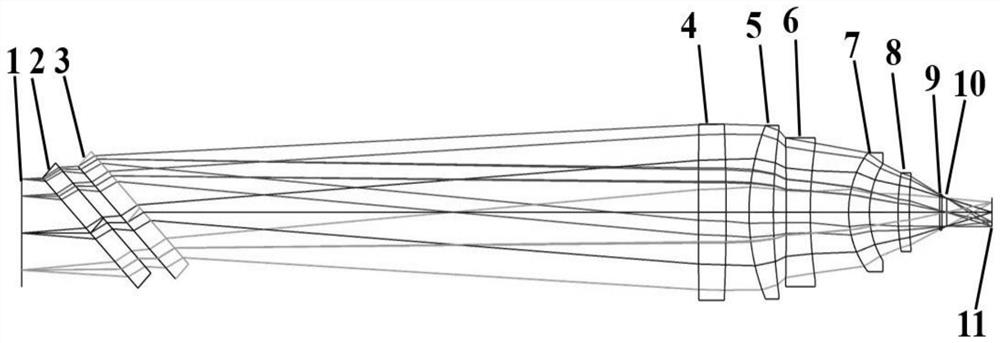
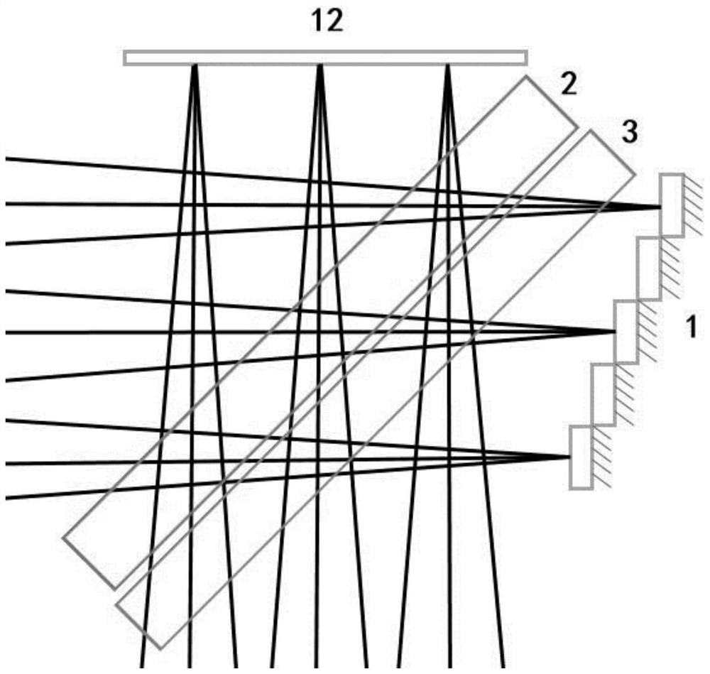
[0027] Specific implementation mode 1. Combination Figure 1 to Figure 9 Describe this embodiment, the optical passive athermal difference secondary imaging system of the medium-wave infrared Fourier transform imaging spectrometer, its working band is 3-5 μm; Surface) 1, beam splitter 2, compensation plate 3, first lens 4, second lens 5, third lens 6, fourth lens 7, fifth lens 8, detector window 9, detector cold stop 10 and Detector front (image plane) 11.

[0028] The incident light passes through the stepped micro-mirror 1, passes through the beam splitter 2 and the compensation plate 3, then passes through the first lens 4, the second lens 5, the third lens 6, the fourth lens 7 and the fifth lens 8, and then passes through the detector The window 9 and the detector cold stop 10 are finally imaged on the detector array (image plane) 11 .

[0029] In this embodiment, the beam splitter 2 and the compensating plate 3 are both flat plates made of zinc selenide, the first lens ...


PUM

PropertyMeasurementUnit
thicknessaaaaaaaaaa
thicknessaaaaaaaaaa
thicknessaaaaaaaaaa

Abstract

An athermal difference secondary imaging system for a mid-wave infrared Fourier transform imaging spectrometer, which relates to the field of spectral imaging technology and solves the shortcomings of the existing infrared optical system athermal difference technology, including stepped micro-mirrors, beam splitters, and compensation plates , five lenses, a detector window, a detector cold stop and a detector front; the present invention solves the power distribution equation, the system defocus equation and the material thermal expansion and lens barrel thermal expansion equations caused by the change of the refractive index of the lens, using The three materials of chalcogenide glass, germanium and silicon are combined with each other to realize the passive heat dissipation function. The system realizes the passive adiabatic function in the temperature range of -20°C-60°C, the relative illumination at the edge of the image plane is close to 90%, the distortion is less than 0.4%, the passivation value at 17lp / mm is close to the diffraction limit, and the depth of field of the system satisfies The total height of the step mirror, the design results show that when the object plane is imaged at different step height positions, the maximum change rate of the system MTF value does not exceed 1%. The system achieves 100% cold stop matching without vignetting.

Description

technical field [0001] The invention relates to the technical field of spectral imaging, in particular to a space-time combined modulation type Fourier transform imaging spectrometer athermal difference secondary imaging system working in mid-wave infrared and based on stepped micro-reflectors. Background technique [0002] The vast majority of VOCs gases have obvious characteristic absorption peaks in the mid-wave infrared spectrum. Spectral analysis of them by spectroscopic instruments can quickly identify the type and concentration of pollutants and other information. Compared with prism and grating spectrometer, the Fourier transform imaging spectrometer has the advantage that the detection spectrum can cover the middle and far infrared bands. However, due to the particularity of infrared materials, temperature changes will change the refractive index of materials, the radius and thickness of optical elements, and the spacing between optical elements, resulting in therma...

Claims


Application Information

Patent Timeline
Patent Type & Authority Patents(China)
IPC IPC(8): G01N21/01G01N21/3504G02B27/00
CPCG01N21/01G01N21/3504G01N2021/0112G01N2021/3595G02B27/0025
Inventor 吕金光任俊梁静秋王惟彪秦余欣陶金赵百轩
Owner CHANGCHUN INST OF OPTICS FINE MECHANICS & PHYSICS CHINESE ACAD OF SCI
Why Eureka
Try Eureka