
An anti-warping structure for injection molded parts

A technology of anti-warping and injection molded parts, which is applied in the direction of electrical components, parts of connecting devices, coupling devices, etc., can solve problems such as increasing the size of the mounting surface, unfavorable miniaturization design, and failure of seals, so as to reduce injection molding The effect of reducing the size of the parts, reducing the size of the connector, and reducing the assembly space

Active Publication Date: 2021-10-26
CHINA AVIATION OPTICAL-ELECTRICAL TECH CO LTD
View PDF9 Cites 1 Cited by
  • Summary
  • Abstract
  • Description
  • Claims
  • Application Information

AI Technical Summary

Problems solved by technology

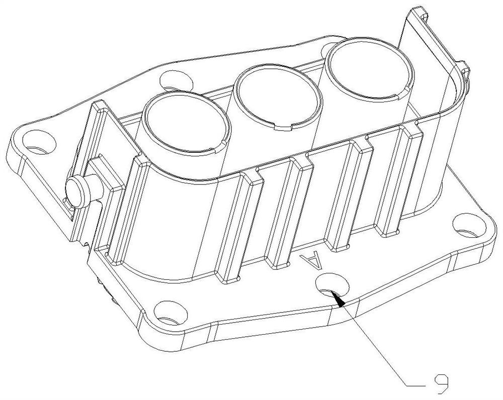
[0002] Injection molded parts have been widely used in low-voltage, high-voltage, signal and integration connectors. When the injection molded parts are released from the mold, they are prone to shrinkage and deformation. In some size restrictions, they will be used longer and have thinner walls. Injection molded parts, the long side of this injection molded part is prone to warping after long-term air exposure and high temperature operation, resulting in the failure of the matching seal
Moreover, long-term warping of injection molded parts will cause cracks or even breakage at the warped parts. In the prior art, the long sides of injection molded parts generally need to arrange bolt positions at intervals, such as figure 1 shown
However, the current structure still cannot change the phenomenon that the long side is prone to warping during long-term use and high-temperature use, and the current structure needs to arrange multiple bolts at intervals. The number of bolts used is large, which indirectly increases the size of the installation surface and occupies a certain amount of space. Not conducive to the overall miniaturization design requirements of the product

Method used


Image

  • An anti-warping structure for injection molded parts
  • An anti-warping structure for injection molded parts
  • An anti-warping structure for injection molded parts

Examples


Embodiment Construction

[0019] In order to further illustrate the technical means and technical effects adopted by the present invention, the present invention will be described in detail below in conjunction with the examples.

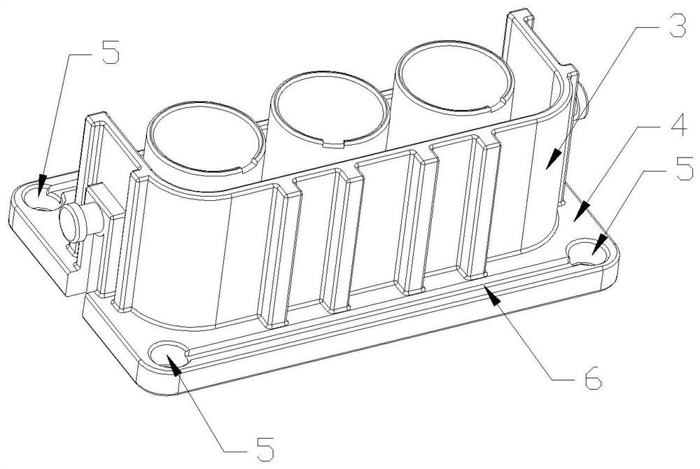
[0020] The anti-warping structure for the injection molded part 3 of the present invention includes a cross bar 1 and through holes I2 arranged at both ends of the cross bar. The through hole I and the cross bar are integrated. The anti-warping structure is made of stainless steel, which is formed as a whole by stamping, and has the characteristics of high hardness and not easy to bend. The surface of the anti-warping structure can also be coated with a layer of coating, which can be nickel-plated layer or zinc-nickel layer or passivation treatment layer to prevent the anti-warping structure from being exposed to the air for a long time or during use The base material is corroded.

[0021] The injection molded part panel 4 used in conjunction with the anti-warping structure...


PUM


Abstract

The invention relates to an anti-warping structure for injection molded parts, which includes a cross bar and through holes I arranged at both ends of the cross bar. The through hole I and the cross bar are integrated. The anti-warping structure is made of stainless steel. It is stamped and formed, and its surface is also provided with a coating layer to prevent the anti-warping structure from being exposed to the air for a long time or the base material from being corroded during use. The panel of the injection molded part is provided with a groove adapted to the anti-warping structure for installing the anti-warping structure. After the injection molded part is assembled with the anti-warping structure, it is fixed to the equipment panel by bolts. The invention can effectively prevent the edge of the injection molded part from warping, even if it is exposed to the air for a long time or used at a high temperature, no warping will occur. At the same time, the invention can reduce the number of screws used, so there is no need to open multiple threaded holes on the edge of the injection molded part, which can reduce the size of the panel of the injection molded part and the volume of the injection molded part, which is beneficial to the overall reduction of the connector volume and the assembly space.

Description

technical field [0001] The invention relates to an anti-warping structure for injection molded parts. Background technique [0002] Injection molded parts have been widely used in low-voltage, high-voltage, signal and integration connectors. When the injection molded parts are released from the mold, they are prone to shrinkage and deformation. In some size restrictions, they will be used longer and have thinner walls. For injection molded parts, the long side of this injection molded part is prone to warping after long-term air exposure and high temperature operation, resulting in the failure of the seal that matches it. Moreover, long-term warping of injection molded parts will cause cracks or even breakage at the warped parts. In the prior art, the long sides of injection molded parts generally need to arrange bolt positions at intervals, such as figure 1 shown. However, the current structure still cannot change the phenomenon that the long side is prone to warping duri...

Claims


Application Information

Patent Timeline
Patent Type & Authority Patents(China)
IPC IPC(8): H01R13/502
CPCH01R13/502
Inventor 符龙强王耀凯董亚东
Owner CHINA AVIATION OPTICAL-ELECTRICAL TECH CO LTD
Learn More