Eureka AIR delivers breakthrough ideas for toughest innovation challenges, trusted by R&D personnel around the world.

Axial surface oil seal used for high-speed motor

A technology of high-speed motors and oil seals, applied in electrical components, electromechanical devices, electric components, etc., can solve problems such as grease smoke in bearing chambers, easy-to-burn bearing safety, and V-rings are easy to fall off, etc., to solve arch warping and cost The effect of low cost and no safety hazard

Inactive Publication Date: 2013-11-13
WUJIANG TIANLONG ELECTRONICS MACHINERY EQUIP
View PDF5 Cites 0 Cited by
  • Summary
  • Abstract
  • Description
  • Claims
  • Application Information

AI Technical Summary

Problems solved by technology

However, when the frame oil seal is used, the contact surface between the frame and the motor shaft rubs, and the friction temperature is higher than 100 degrees, causing the grease in the bearing chamber to smoke, which is easy to burn the bearing and cause safety hazards
When the V-ring is used, if the interference between the V-ring and the motor shaft is more than 5mm, the V-ring will generally crack within three months. If the interference is below 5mm, the V-ring will crack when the motor rotates at high speed. easy to drop

Method used


Image

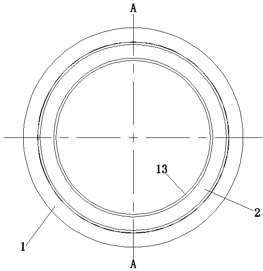
  • Axial surface oil seal used for high-speed motor
  • Axial surface oil seal used for high-speed motor
  • Axial surface oil seal used for high-speed motor

Examples


Embodiment 1

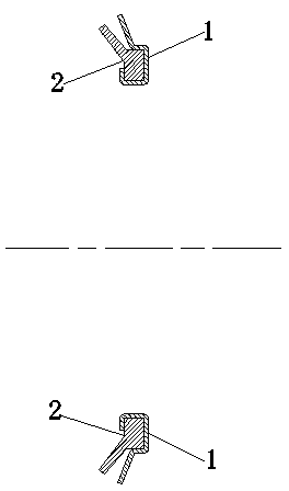
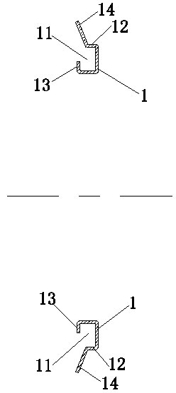
[0019] Such as figure 1 , figure 2 , image 3 , Figure 4 The shaft surface oil seal for high-speed motors shown in the figure has a casing shape that is compatible with the motor shaft surface. Its shape is a ring-shaped metal casing (1). The inner diameter of the ring-shaped metal casing matches the motor shaft. Circumferentially arranged grooves (11), the inner diameter of the ring-shaped metal shell extends vertically upward for a period and then extends horizontally outward to form a buckle structure (13), the outer edge of the bottom of the groove is vertically upward extending in one direction to form a vertical groove outer wall (12), and the outer edge of the top of the groove outer wall extends obliquely outward to form the sealing part protection structure (14) of the rubber ring;

[0020] The rubber ring (1) of the oil seal includes a positioning part (22) and a sealing part (21). The positioning part of the rubber ring is in the shape of a ring, and the height...

Embodiment 2

[0022] Such as Figure 5 The shown embodiment 2 is an oil seal for the shaft end face of a high-speed motor. The shape of its shell is adapted to the end face of the motor shaft. The structure of its rubber ring is consistent with that of embodiment 1. The bending mechanism (15), that is, an L-shaped bending structure (15) is provided extending outward from the outer edge of the sealing portion protection structure of the annular metal casing in Embodiment 1.


PUM


Abstract

The invention discloses an axial surface oil seal used for a high-speed motor. The axial surface oil seal used for the high-speed motor comprises a circular ring-shaped metal casing and a rubber ring, wherein a circle of groove is formed in the periphery of the inner diameter of the circular ring-shaped metal casing; the one section of the outer edge of the groove bottom upwards extends in a vertical direction to form a circumference of vertical groove wall; the outer edge of the top of the vertical groove wall extends in outward oblique direction to form a sealing protective structure of the rubber ring; a positioning part of the rubber ring is circular ring-shaped, the height of the positioning part is matched with the vertical groove wall of the groove, and the width of the bottom of the positioning part is matched with the width of the groove; the top of the positioning part extends in the outward oblique direction to form a sealing part; and the part between the inner diameter of the bottom of the sealing part and the inner diameter of the top of the positioning part forms a buckling surface of the rubber ring, and the buckling surface is matched with a buckling structure. The axial surface oil seal is applicable to the high-speed motor, and is simple in structure, low in manufacturing cost, long in service life and obvious in effect.

Description

technical field [0001] The invention relates to a sealing structure of a motor, in particular to an oil seal suitable for a high-speed motor. Background technique [0002] The patent authorized by the inventor with the notification number CN2662520Y discloses a special axial surface oil seal for motors. The oil seal with this structure cannot be applied to high-speed motors. When the shaft diameter of the motor is greater than 70 mm and the speed is 3000 rpm, the rubber ring will Disengagement occurs. Because the higher the speed of the motor, the larger the diameter of the motor shaft, the greater the centrifugal force on the rubber ring in the oil seal when the motor rotates, and the easier it is to separate from the metal ring shell and become a strip of rubber. For oil seals with this structure, the bottom end surface of the metal ring shell is prone to arching. When the arching is 0.3mm, the machine will be deflected when the machine moves, causing the temperature to r...

Claims


Application Information

Patent Timeline
Patent Type & Authority Applications(China)
IPC IPC(8): H02K5/16
Inventor 王俊华沈岳李红军
Owner WUJIANG TIANLONG ELECTRONICS MACHINERY EQUIP
Why Eureka
Eureka Blog
Learn More