Eureka AIR delivers breakthrough ideas for toughest innovation challenges, trusted by R&D personnel around the world.

Flat plate type sander connected to dust collection device

A technology of dust collection device and flat plate, which is applied in the field of sanding machines, can solve the problems of dust environment, human hazards, poor dust collection effect, etc., and achieve the effects of improving the use environment, saving costs, and high dust collection rate

Inactive Publication Date: 2016-10-05
SUZHOU BOLAIXI ELECTRICAL APPLIANCE CO LTD
View PDF8 Cites 1 Cited by
  • Summary
  • Abstract
  • Description
  • Claims
  • Application Information

AI Technical Summary

Problems solved by technology

[0002] The sanding machine drives the bottom plate to swing through the driving component, and uses the sandpaper clamped on the bottom plate to grind or polish the surface of the workpiece. Dust collection devices such as dust collection bags are installed at the rear of the housing. There will still be a lot of dust in the working environment of this type of sander, and the dust collection effect is poor.

Method used


Image

  • Flat plate type sander connected to dust collection device
  • Flat plate type sander connected to dust collection device
  • Flat plate type sander connected to dust collection device

Examples


Embodiment 1

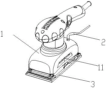
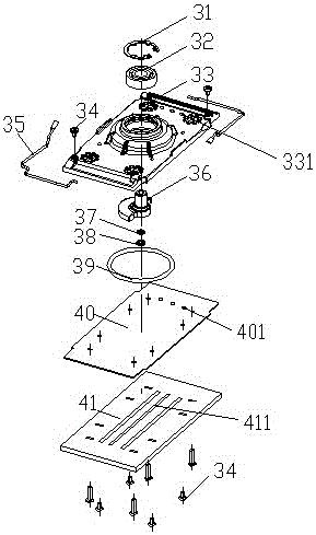
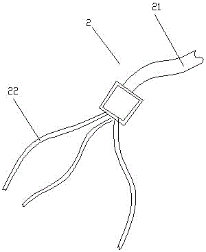
[0026] Such as Figure 1-3 As shown, a flat sand connected with a dust suction device includes a bottom plate assembly 3, a casing 1, a drive assembly and an eccentric assembly located in the casing 1, and the drive assembly drives the bottom plate assembly 3 to swing eccentrically through the eccentric assembly. , the base plate assembly 3 includes a base plate 33 and a base pad 41 arranged up and down, the base pad 41 is provided with a dust removal groove 411, and there are three dust removal grooves 411, and the base plate 33 has a first through hole 331 communicating with the dust removal groove 411, The number of the first through holes 331 is also 3, and the sander also has a gas pipe passing through the first through holes 331 or the end is flush with the bottom of the first through holes 331, and the gas pipe has a main pipe 21 and is connected with the bottom of the first through hole 331. The main pipe 21 communicates with the branch pipes 22 , the number of the bra...

Embodiment 2

[0032] Such as Figure 4 As shown, in Embodiment 2, the strip-shaped dust removal groove 411 is arranged side by side in the floor pad 41 along the length direction of the bottom pad 41, the first through hole 331, the fourth through hole 401 in the bottom plate assembly 3, and the second through hole on the sandpaper. The hole and the third through hole are adjusted accordingly with the change of the position of the dust removal groove 411, and the rest of the structure is the same as that of Embodiment 1.

Embodiment 3

[0034] Such as Figure 5 As shown, in Embodiment 3, the dust removal grooves 411 are arranged in an umbrella-shaped manner in the bottom plate pad 41, the first through hole 331, the fourth through hole 401 in the bottom plate assembly 3, and the second through hole and the third through hole on the sandpaper Corresponding adjustments are made as the position of the dust removal tank 411 changes, and the rest of the structure is the same as that of Embodiment 1.


PUM


Abstract

The invention discloses a flat sand connected with a dust suction device, which comprises a bottom plate assembly, a casing, a drive assembly and an eccentric assembly located in the casing, the drive assembly drives the bottom plate assembly to swing eccentrically through the eccentric assembly, and the bottom plate assembly includes bottom plates arranged up and down And the bottom plate pad, the bottom plate pad is provided with dust removal grooves, the dust removal grooves have 2-5, the bottom plate has the first through hole communicating with the dust removal groove, the number of the first through holes is equal to the number of dust removal grooves, and the sander also has the function of passing through the first through hole A through hole or an air pipe whose end is flush with the bottom of the first through hole. The air pipe has a main pipe and branch pipes communicating with the main pipe. The number of branch pipes is equal to the number of the first through holes. The flat sand of the invention has a simple structure, is connected with an external dust collection device such as a vacuum cleaner, and has high dust collection efficiency. Compared with the existing sanding machine, the use environment can be obviously improved, and the cost can be saved.

Description

technical field [0001] The invention relates to a sander, in particular to a flat sander connected with a dust suction device. Background technique [0002] The sanding machine drives the bottom plate to swing through the driving component, and uses the sandpaper clamped on the bottom plate to grind or polish the surface of the workpiece. Dust collection devices such as dust collection bags are installed at the rear of the housing. There will still be a lot of dust in the working environment of this type of sander, and the dust collection effect is poor. Contents of the invention [0003] The technical problem to be solved by the present invention is to overcome the defects of the prior art and provide a flat sand with a dust suction device. The dust suction device in the flat sand has a simple structure, the overall device has high dust suction efficiency, and can improve the environment for customers to use. . [0004] In order to solve the problems of the technologies...

Claims


Application Information

Patent Timeline
Patent Type & Authority Applications(China)
IPC IPC(8): B24B23/00B24B55/10
CPCB24B23/00B24B55/105
Inventor 徐超
Owner SUZHOU BOLAIXI ELECTRICAL APPLIANCE CO LTD
Why Eureka
Eureka Blog
Learn More