Eureka AIR delivers breakthrough ideas for toughest innovation challenges, trusted by R&D personnel around the world.

An Improved Ribbon Loom with Stable Weft Insertion

A ribbon weaving machine and weft insertion technology, which is applied to looms, small looms, textiles, etc., can solve the problems of pulling out yarn bobbins, hitting nearby operators, and insufficient technical considerations, etc., to achieve increased resistance and improved The effect of production safety

Active Publication Date: 2020-07-24
杭州江南世家药业有限公司
View PDF5 Cites 0 Cited by
  • Summary
  • Abstract
  • Description
  • Claims
  • Application Information

AI Technical Summary

Problems solved by technology

[0002] In modern industrial production, ribbons are often used in the production of luggage, clothing, shoes and hats. Ribbons have become an indispensable part of clothing production, so the demand for ribbons is increasing. Textile factories generally use ribbon machines for processing and production, but the current technology The consideration is not perfect, and has the following disadvantages: 1. When the traditional ribbon loom is used, the yarn bobbin is usually evenly placed on the yarn rack, and then drawn into the textile mechanism through the wire structure for processing and weaving. However, as the ribbon loom works and the yarn After the remaining amount of yarn in the tube decreases, the quality of the yarn tube becomes lighter and lighter. Therefore, when the high-speed loom suddenly stops, the yarn in the yarn tube will continue to rotate under the action of inertia and throw out the excess yarn. In turn, different yarns are entangled together, which requires manual finishing, which increases the workload of the operator and reduces the production efficiency of the ribbon; If the yarn bobbin and the fixing rod are not fully fixed, the yarn bobbin may be thrown out by the yarn and hit the nearby operators, which is dangerous

Method used

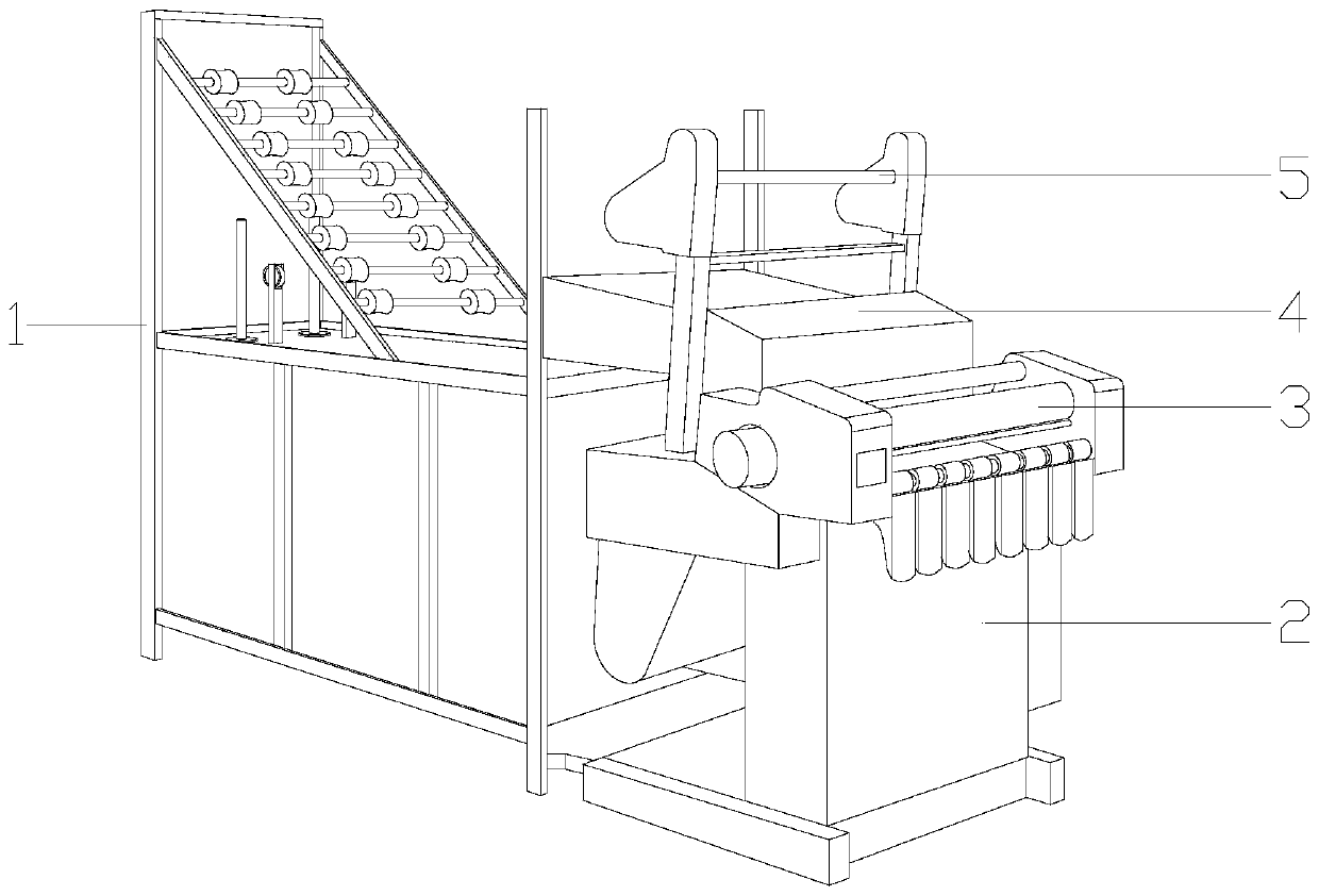
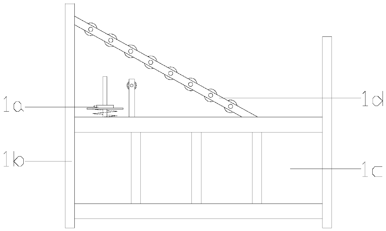
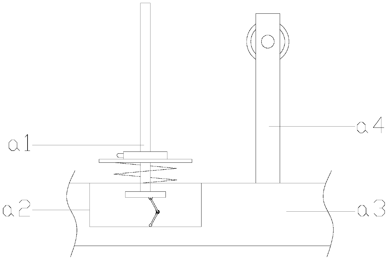

Image

  • An Improved Ribbon Loom with Stable Weft Insertion
  • An Improved Ribbon Loom with Stable Weft Insertion
  • An Improved Ribbon Loom with Stable Weft Insertion

Examples


Embodiment

[0031] see Figure 1-Figure 3 , the present invention provides an improved loom for weft insertion, the structure of which includes a pay-off mechanism 1, a loom body 2, a ribbon delivery mechanism 3, a textile mechanism 4, and a directional yarn feeder 5, and the loom body 2 is vertically Installed in the textile workshop, the ribbon conveying mechanism 3 is located at the front top of the ribbon machine main body 2, the textile mechanism 4 is located behind the ribbon conveying mechanism 3 and is mechanically connected to the ribbon conveying mechanism 3, and the bottom of the directional yarn feeder 5 is connected to the textile The left and right sides of the mechanism 4 are fixed together by bolts. The pay-off mechanism 1 is located on the left side of the main body 2 of the loom. The thread guide roller 1d is composed of the right end of the three-dimensional fixed frame 1b and the main body of the loom 2 through bolts. Below the bobbin holder 1a inside the frame 1b, th...


PUM


Abstract

The invention discloses an improved webbing loom with a stable weft insertion function. The improved webbing loom with the stable weft insertion function structurally comprises a paying-off mechanism,a webbing loom main body, a webbing conveying mechanism, a spinning mechanism and a directional yarn feeder; a linear paying-off device is installed on the webbing loom, and when the webbing loom works, a bobbin can be fixed with a bobbin fixing rod through negative-pressure suction, the situation that the bobbin is pulled out and flung away by yarn and hits a nearby operator when the webbing loom works at high speed is prevented, and the safety of the webbing loom is improved; meanwhile, the resistance of the rotary output of the bobbin can be linearly adjusted according to the remaining amount of the yarn, the situation that when the webbing loom suddenly shuts down, the yarn in the bobbin continues to rotate under the inertia effect, so that the excess yarn is flung away and entangledis avoided, the workload of managing the yarn by the operator is reduced, and the webbing production efficiency is improved.

Description

technical field [0001] The invention relates to a weaving ribbon equipment, in particular, an improved weaving ribbon machine with stable weft insertion. Background technique [0002] In modern industrial production, ribbons are often used in the production of luggage, clothing, shoes and hats. Ribbons have become an indispensable part of clothing production, so the demand for ribbons is increasing. Textile factories generally use ribbon machines for processing and production, but the current technology The consideration is not perfect, and has the following disadvantages: 1. When the traditional ribbon loom is used, the yarn bobbin is usually evenly placed on the yarn rack, and then drawn into the textile mechanism through the wire structure for processing and weaving. However, as the ribbon loom works and the yarn After the remaining amount of yarn in the tube decreases, the quality of the yarn tube becomes lighter and lighter. Therefore, when the high-speed loom suddenly ...

Claims


Application Information

Patent Timeline
Patent Type & Authority Patents(China)
IPC IPC(8): D03D35/00D03D49/16
CPCD03D35/00D03D49/16
Inventor 谢雄星邱惠峰
Owner 杭州江南世家药业有限公司
Why Eureka
Eureka Blog
Learn More