
A MEMS switch

A micro-electro-mechanical system and switch technology, which is applied in circuits, relays, electrical components, etc., can solve the problem that the floating end of the cantilever beam is prone to warping and other problems

Active Publication Date: 2018-09-21
BEIJING UNIV OF POSTS & TELECOMM
View PDF3 Cites 0 Cited by
  • Summary
  • Abstract
  • Description
  • Claims
  • Application Information

AI Technical Summary

Problems solved by technology

[0005] The purpose of the embodiments of the present invention is to provide a micro-electromechanical system switch to solve the problem that the floating end of the cantilever beam is prone to warping in the existing MEMS switch using a cantilever beam with a low elastic coefficient

Method used


Image

  • A MEMS switch
  • A MEMS switch
  • A MEMS switch

Examples


Embodiment Construction

[0026] The following will clearly and completely describe the technical solutions in the embodiments of the present invention with reference to the accompanying drawings in the embodiments of the present invention. Obviously, the described embodiments are only some, not all, embodiments of the present invention. Based on the embodiments of the present invention, all other embodiments obtained by persons of ordinary skill in the art without creative efforts fall within the protection scope of the present invention.

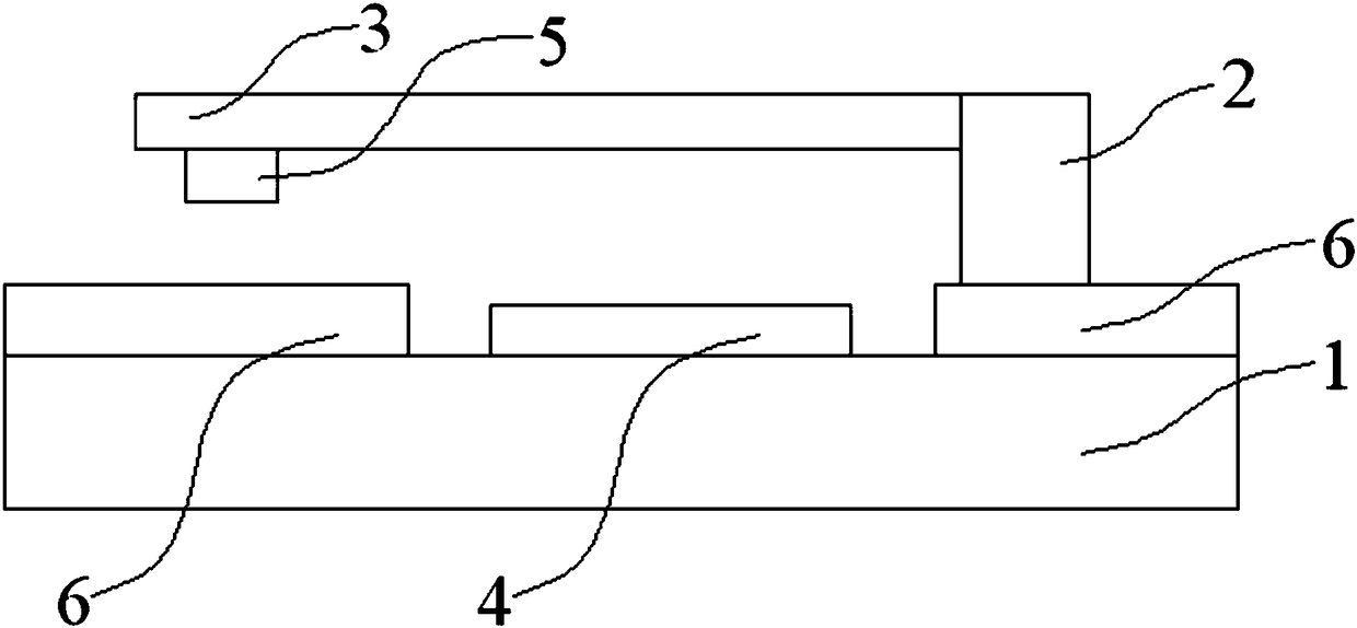
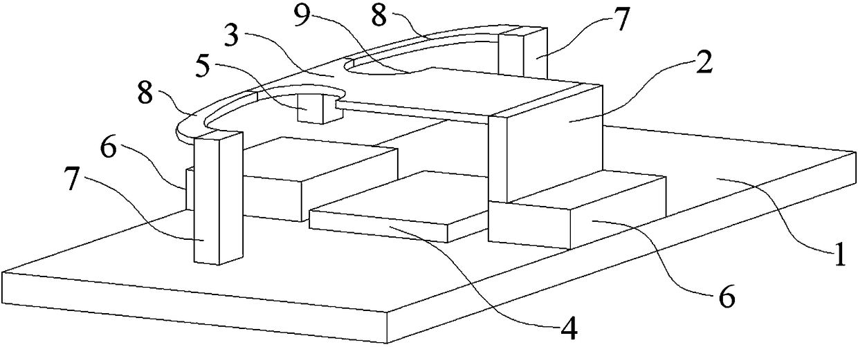
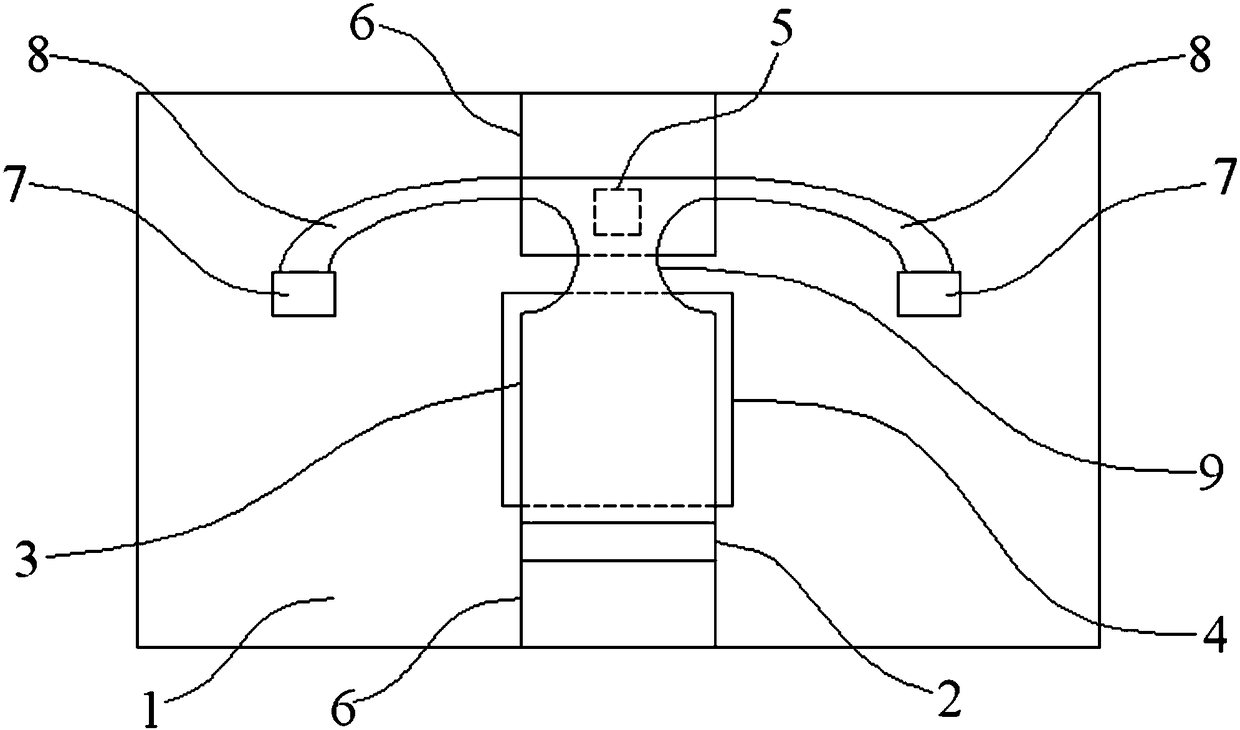
[0027] Such as Figure 2~4 As shown, a MEMS switch provided by an embodiment of the present invention includes a main anchor area 2, a cantilever beam 3, a contact 5, a bottom electrode 4, two auxiliary anchor areas 7 and a side beam 8,

[0028] The main anchorage area 2 is arranged on one of the conductor lines 6 which are disconnected into two sections;

[0029] The contact 5 corresponds to another conductor line 6, and the conductor line 6 is arranged on the su...


PUM


Abstract

The embodiment of the invention discloses a switch of a micro electro mechanical system.The switch comprises a main anchor area, a cantilever beam, a contact, a bottom electrode, two auxiliary anchor areas and a side beam.The main anchor area is arranged on one of two separated conductor wires, and the contact corresponds to the other conductor wire.The conductor wires are arranged on a substrate.One end of the cantilever beam is fixed to the main anchor area.The contact is arranged on the lower surface of the suspension end of the cantilever beam.The bottom electrode is arranged on the substrate and corresponds to the position below the cantilever beam.The auxiliary anchor areas are arranged on the substrate.The two auxiliary anchor areas are correspondingly arranged on the two sides of the cantilever beam.The top ends of the auxiliary anchor areas are connected to one end of the side beam, and the other end of the side beam is connected with the suspension end of the cantilever beam.By means of the scheme, the problem that in an existing MEMS switch adopting a cantilever beam low in elastic coefficient, the suspension end of the cantilever beam is prone to warping is solved.

Description

technical field [0001] The invention relates to the technical field of radio frequency micro-electro-mechanical systems, in particular to a micro-electro-mechanical system switch. Background technique [0002] With the continuous development of communication technology, electromagnetic waves have gradually developed from low frequency and high frequency ranges to radio frequency and microwave ranges. Compared with traditional switches, RF MEMS (Micro-Electro-Mechanical System) switches have the advantages of low insertion loss, high isolation, low power and low cost. Therefore, RF MEMS switches are increasingly used It is used in tunable filters, antennas, matching networks and other equipment. Low driving voltage MEMS switch is a commonly used type of RF MEMS switch. Compared with high driving voltage MEMS switch, the power supply circuit module using low driving voltage MEMS switch can have a smaller size, which is very conducive to the miniaturization of communication eq...

Claims


Application Information

Patent Timeline
Patent Type & Authority Patents(China)
IPC IPC(8): H01H59/00
CPCH01H59/0009
Inventor 邓中亮魏浩郭旭兵甘俊
Owner BEIJING UNIV OF POSTS & TELECOMM
Learn More