
Self-lubricating and high-wear-resistance non-metal sealing sliding block and manufacturing method thereof

A sealing slider and self-lubricating technology, which is applied in the direction of engine sealing, chemical instruments and methods, sustainable manufacturing/processing, etc., can solve the problems of inability to dry-run air pumps, low toughness of graphite materials, and insufficient self-lubricating properties , to achieve the effect of breaking through the shackles of formula design and production methods, increasing the hardness, and making the production methods simple and feasible

Active Publication Date: 2020-04-21
合肥一密科技有限公司
View PDF10 Cites 0 Cited by
  • Summary
  • Abstract
  • Description
  • Claims
  • Application Information

AI Technical Summary

Problems solved by technology

However, the graphite material has low toughness, is brittle, and is not resistant to bending; the filled PTFE material has low hardness, insufficient heat resistance, and is easily deformed by heat.
Thermosetting resin materials have insufficient self-lubrication and excessive wear
Therefore, none of the above three materials can be used in depth on dry-running air pumps.

Method used


Image

  • Self-lubricating and high-wear-resistance non-metal sealing sliding block and manufacturing method thereof
  • Self-lubricating and high-wear-resistance non-metal sealing sliding block and manufacturing method thereof
  • Self-lubricating and high-wear-resistance non-metal sealing sliding block and manufacturing method thereof

Examples


Embodiment 1

[0043] S1, weaving

[0044] Get the alkali-free glass fiber yarn of 45 parts by weight, weave on weaving equipment, become the fiber sheet of plain weave, the thickness of fiber sheet is 0.1mm, and the pore size is 0.5mm;

[0045] S2, mixing

[0046] 3 parts by weight of silicon nitride powder (particle size 20nm) and 75 parts by weight of polytetrafluoroethylene resin emulsion (solid content is 55%) are metered into the mixing chamber of the ultrasonic stirring homogenizer, the equipment is turned on, and mixed for 10 minutes , observe with the naked eye whether there is agglomeration phenomenon, if not, get a mixed emulsion;

[0047] S3, impregnation, pre-sintering

[0048] Measure the mixed emulsion prepared by S2 into the pool of the dipping heat treatment machine, put the glass fiber woven sheet into the designated position of the pool, start impregnation, take it out from the pool after soaking for 3 minutes, and enter the drying area at 100 °C , dry for 8 minutes, th...

Embodiment 2

[0052] S1, weaving

[0053] Get 43 parts by weight of carbon fiber yarn and weave it on a weaving device to form a twill-shaped carbon fiber sheet with a thickness of 0.1mm and a pore size of 0.5mm;

[0054] S2, mixing

[0055] 5 parts by weight of silicon oxide powder (particle diameter 20nm) and 65 parts by weight of polytetrafluoroethylene resin emulsion (solid content is 65%) are metered into the mixing chamber of the ultrasonic stirring homogenizer, the equipment is turned on, and mixed for 10 minutes. Observe with the naked eye whether there is any agglomeration, and if there is no agglomeration, a mixed emulsion will be obtained;

[0056] S3, impregnation, pre-sintering

[0057] Pour the mixed emulsion into the material tank of the dipping and heat treatment machine, put the carbon fiber woven sheet into the designated position of the material tank, and start to impregnate. Then enter the drying zone at 320°C, bake for 5 minutes, and finally enter the pre-sintering z...

Embodiment 3

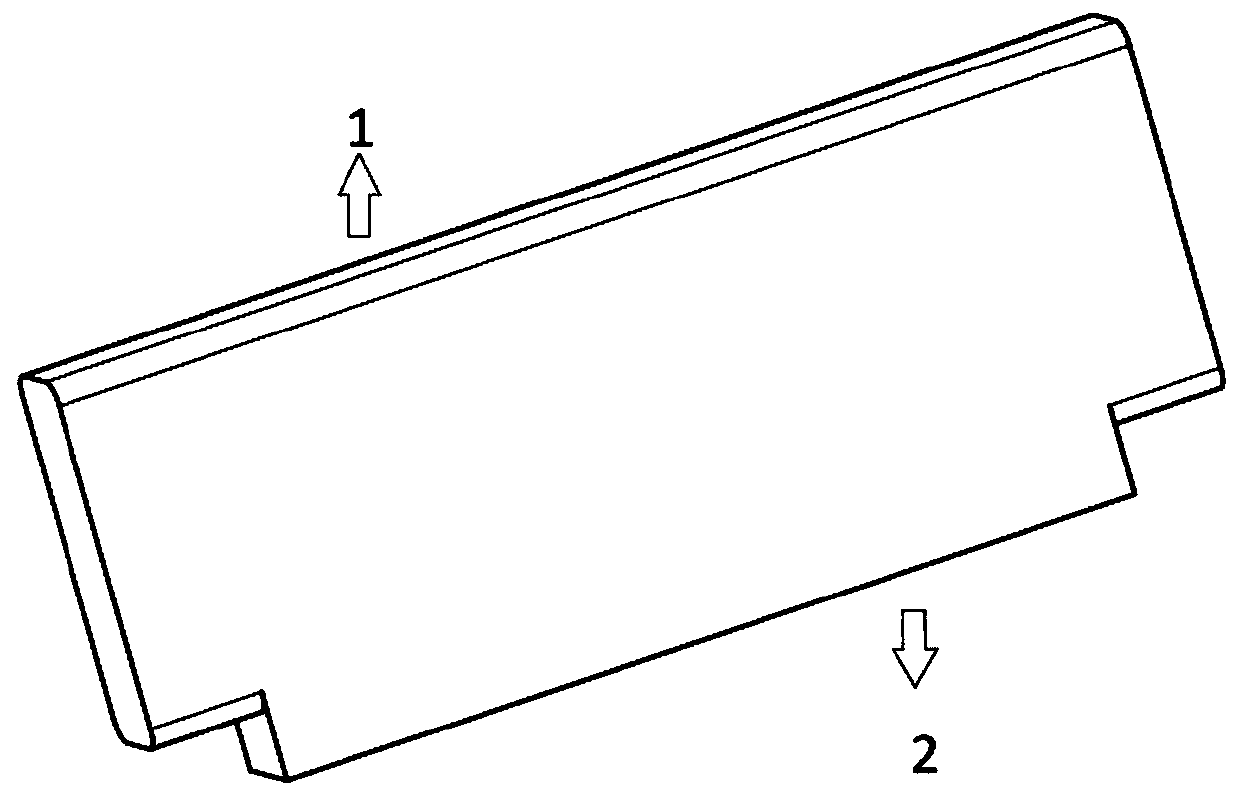
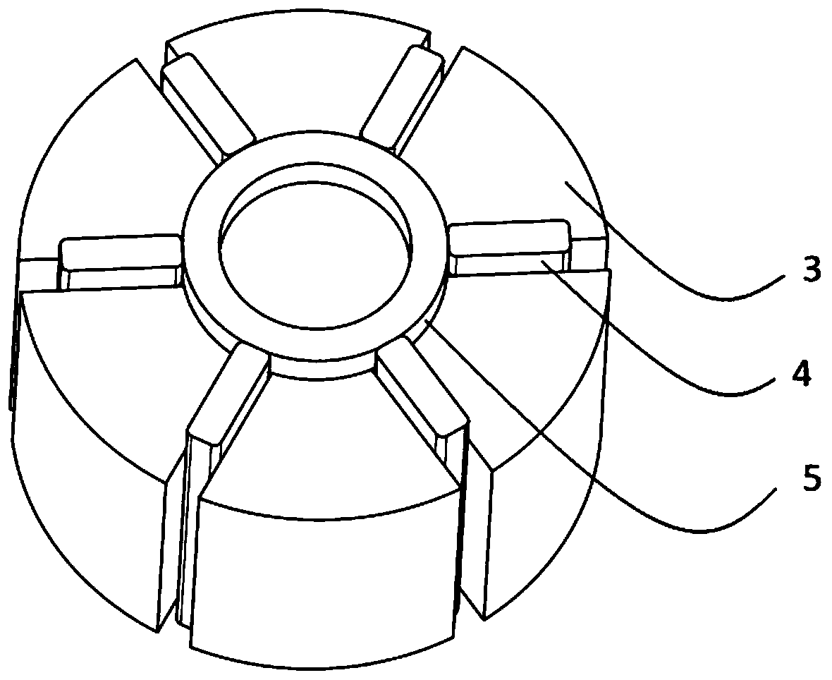
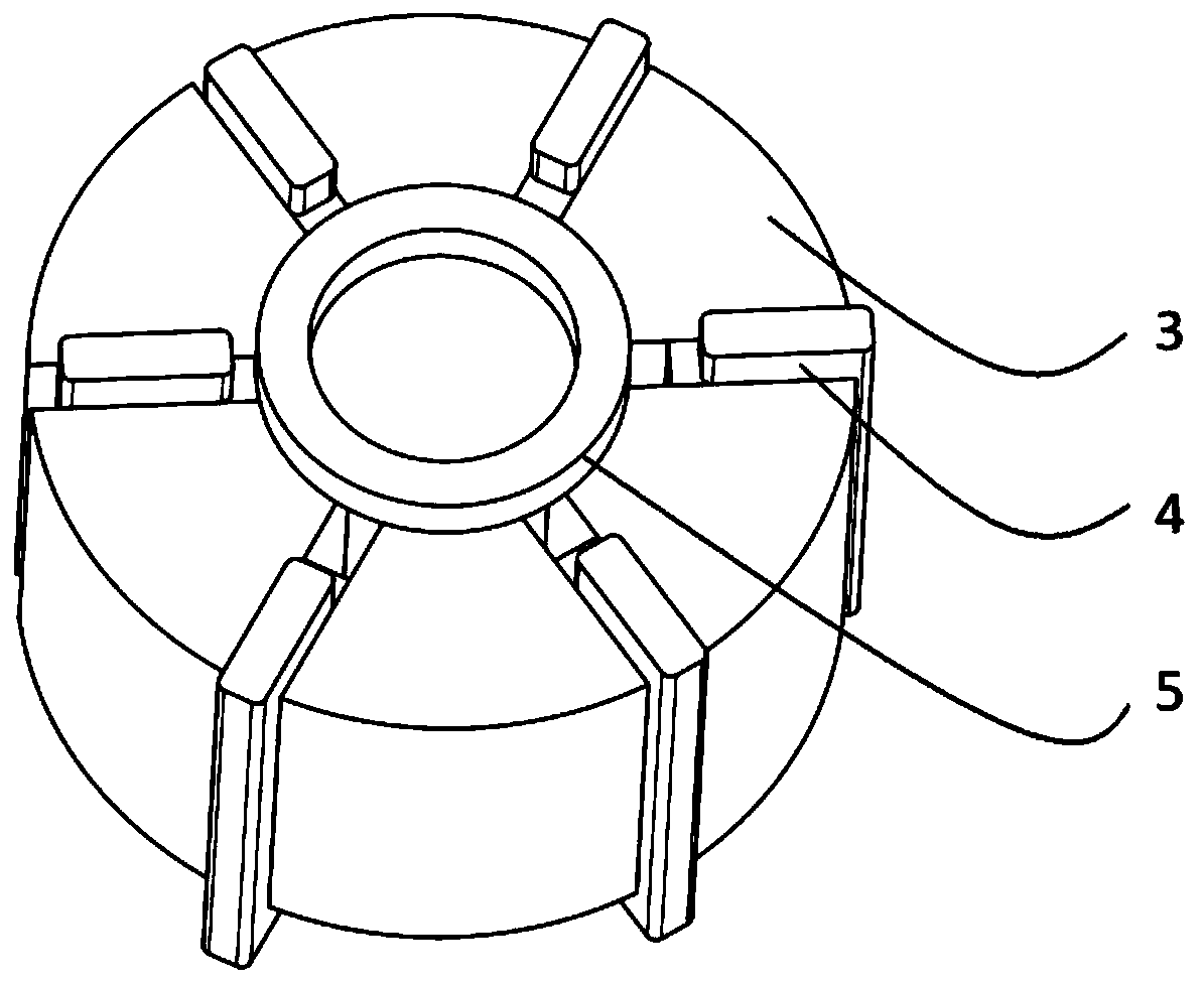
[0079] Such as figure 1 , install the "T" shaped seal slider produced by the embodiment of the present invention in the axial groove of the eccentric rotor 3, the force-bearing surface 2 faces the center of the eccentric rotor 3, the sealing surface 1 faces the cylinder, and the force-bearing surface 2 is close to In spacer ring 5, see the specific location figure 2 . Such as image 3 As shown, when the eccentric rotor 3 starts to rotate, the sealing slider 4 moves toward the cylinder side under the action of centrifugal force, the sealing surface 1 is in contact with the cylinder, and the moving distance of the sealing slider 4 in each groove is different. Under the action of the cylinder, a circular trajectory is always maintained, and a certain space is formed between the eccentric rotor 3, the sealing slider 4 and the cylinder, and the volume of the space changes periodically, so as to achieve the effects of vacuuming and gas compression.


PUM

PropertyMeasurementUnit
particle diameteraaaaaaaaaa
thicknessaaaaaaaaaa
sizeaaaaaaaaaa

Abstract

The invention discloses a self-lubricating and high-wear-resistance non-metal sealing sliding block and a manufacturing method thereof, and belongs to the field of sealing materials. The sealing sliding block comprises the following components in parts by weight: 40-50 parts of non-metal inorganic fiber yarn, 40-55 parts of self-lubricating resin and 3-5 parts of inorganic ceramic powder. The manufacturing method of the sealing sliding block comprises weaving, mixing, dipping, presintering, alternate laying, hot pressing, demolding and the like. The invention further discloses a T-shaped sealing sliding block for an air pump, and efficient vacuumizing can be achieved after a unit operates. The sealing sliding block prepared by the invention has excellent self-lubricating property and wearresistance and is high in rigidity, not prone to bending and capable of meeting the sealing requirement under the high-speed and dry friction working condition, gas in a pipeline connected with the air pump cavity can be rapidly exhausted after a unit operates, so that pipeline vacuum is achieved and the purpose of rapidly pumping other media is achieved, the whole operation process is efficient and energy-saving, and no pollution is caused to other media and the environment.

Description

technical field [0001] The invention belongs to the field of sealing, specifically relates to a non-metallic sealing slider with performance characteristics such as self-lubrication, high wear resistance, and bending resistance, and discloses the material composition, manufacturing method and "T" shape structure of the sealing slider. Background technique [0002] The sealing slider is a key part of the vane air pump, which is located in several axial grooves of the eccentric rotor and can slide freely in the radial direction. Since the rotor is arranged eccentrically in the cylinder, a crescent-shaped space is formed between the inner wall of the cylinder and the outer surface of the rotor. When the rotor rotates, the slider is thrown out of the groove by the centrifugal force, and its end is close to the inner circular wall of the cylinder. The crescent-shaped space is divided into several fan-shaped small chambers by the slider - the volume of the basic unit, and the slid...

Claims


Application Information

Patent Timeline
Patent Type & Authority Applications(China)
IPC IPC(8): B32B27/30B32B27/28B32B37/06B32B37/10B32B17/02B32B17/10B32B9/00B32B9/04C08L27/18C08K7/14C08K3/34C08K7/06C08K3/36F16J15/16
CPCB32B5/024B32B27/12B32B27/28B32B27/304B32B37/06B32B37/10B32B2260/021B32B2260/046B32B2262/101B32B2262/106B32B2307/306B32B2307/536B32B2307/546B32B2307/554B32B2307/558C08K3/34C08K3/36C08K7/06C08K7/14C08K2201/011C08L2201/08F16J15/164C08L27/18Y02P20/10
Inventor 杨家义钱蜜蜜
Owner 合肥一密科技有限公司
Learn More