An energy-saving plate stamping part
A stamping and energy-saving technology, applied in the field of energy-saving plate-shaped stamping parts, can solve the problems of single workpiece stamping, easy displacement of stamping, waste of time, etc., and achieve the effects of ensuring stability, ensuring precision, and reducing errors.
- Summary
- Abstract
- Description
- Claims
- Application Information
AI Technical Summary
Problems solved by technology
Method used
Image
Examples
Embodiment 1
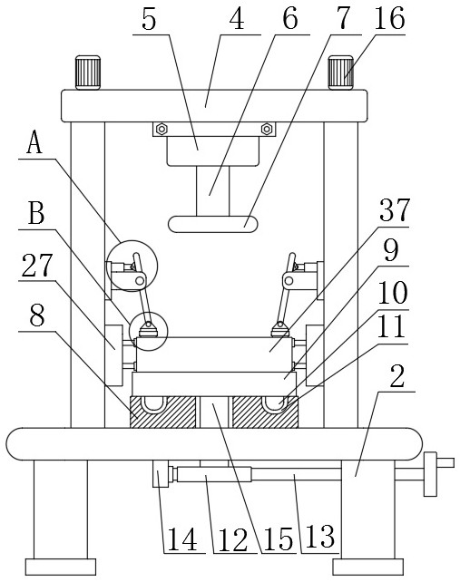
[0025] see figure 1 , figure 2 , image 3 and Figure 4 , an energy-saving plate-shaped stamping part, an energy-saving plate-shaped stamping part, including a base 1; support columns 2 are fixedly connected around the bottom end of the base 1, and the top end of the base 1 passes through a connecting plate 3 It is fixedly connected with the top seat 4; the top seat 4; the bottom end of the top seat 4 is fixedly connected with a hydraulic cylinder 5, and the piston rod 6 of the hydraulic cylinder 5 is fixedly connected with a stamping die 7 by bolts, which is used to press the workpiece body 37 for stamping; workbench 8; said workbench 8 is fixedly connected on the base 1, and the top of said workbench 8 is provided with a lower mold base 9, said lower mold base 9 is provided with a workpiece body 37; height adjustment mechanism; the height adjustment mechanism is connected to the connection plate 3, the height adjustment mechanism includes a motor 16, a threaded rod 17, a...
Embodiment 2
[0037] As a preferred solution of Embodiment 1, please refer to figure 1 , the angle adjustment mechanism includes an annular slide bar 10, an annular chute 11, a rotating shaft 15, a worm gear 12 and a worm 13, an annular chute 11 is opened on the worktable 8, and the bottom end of the lower mold base 9 passes through an annular The slide bar 10 is slidably connected to the annular chute 11, one end of the rotating shaft 15 is fixedly connected to the lower mold base 9, and the other end of the rotating shaft 15 passes through the base 1 and is fixedly connected to the turbine 12, and the worm 13 passes through the mounting seat 14 is rotatably connected to the bottom end of the base 1, and the worm gear 12 is matched with the worm 13;
[0038] One end of the worm 13 is fixedly connected with a rotating handle;
[0039] Wherein, the lower mold base 9 can drive the workpiece body 37 to rotate and adjust the angle by sliding in the annular chute 11 through the annular slide ba...
Embodiment 3
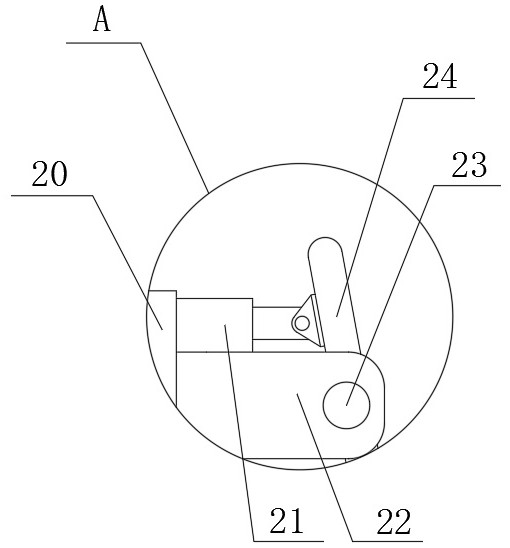
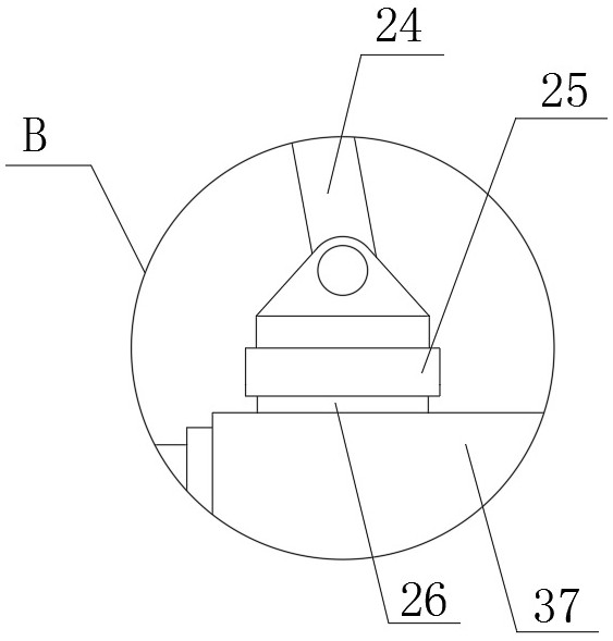
[0042] As a preferred solution of Embodiment 1 or Embodiment 2, please refer to figure 1 and Figure 5 , the shock absorbing mechanism includes a housing 27, a slide plate 28, a connecting column 29, a partition 30, a first spring 31, a second spring 32, an adjusting column 35, a rotating shaft 36, a connecting rod 33 and a rotating column 34, the The housing 27 is fixedly connected to the connecting plate 3 and is located above the workbench 8. The partition plate 30 is fixedly connected in the housing 27, the slide plate 28 is slidably connected in the housing 27, and one end of the adjusting column 35 is connected to the housing 27. The slide plate 28 is fixedly connected, and the other end of the adjustment column 35 passes through the partition 30 and is located between the inner wall of the housing 27 and the partition 30. Two connecting rods 33 are provided, and one end of the two connecting rods 33 The rotating shaft 36 is rotatably connected with the adjustment colum...
PUM
 Abstract
Description
Claims
Application Information
 - Generate Ideas
- Intellectual Property
- Life Sciences
- Materials
- Tech Scout
- Unparalleled Data Quality
- Higher Quality Content
- 60% Fewer Hallucinations
Browse by: Latest US Patents, China's latest patents, Technical Efficacy Thesaurus, Application Domain, Technology Topic, Popular Technical Reports.
© 2025 PatSnap. All rights reserved.Legal|Privacy policy|Modern Slavery Act Transparency Statement|Sitemap|About US| Contact US: help@patsnap.com


