
The electromagnetic valve

A solenoid valve, electromagnetic technology, applied in the direction of diaphragm valve, valve device, valve details, etc., can solve the problem of high cost

Active Publication Date: 2021-09-07
SAGINOMIYA SEISAKUSHO INC
View PDF2 Cites 0 Cited by
  • Summary
  • Abstract
  • Description
  • Claims
  • Application Information

AI Technical Summary

Problems solved by technology

However, the above-mentioned separate device requires installation space other than the solenoid valve, and becomes a factor of high cost.

Method used


Image

  • The electromagnetic valve
  • The electromagnetic valve
  • The electromagnetic valve

Examples


Embodiment Construction

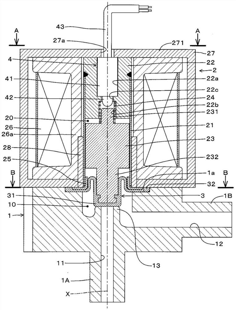
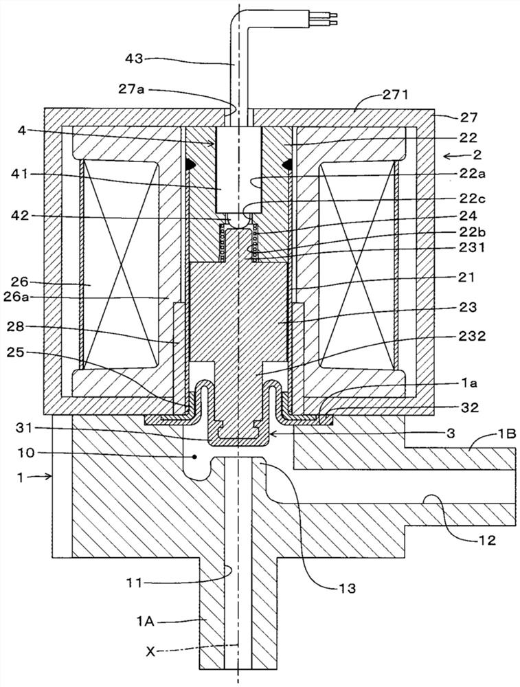
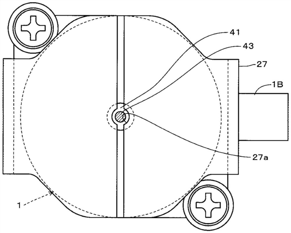
[0025] Next, embodiments of an electromagnetic actuator and an electromagnetic valve according to the present invention will be described with reference to the drawings. figure 1 It is a vertical cross-sectional view of the solenoid valve of the embodiment when it is not energized (valve closed state), figure 2 It is a longitudinal sectional view of the solenoid valve when it is energized (valve open state), image 3 is showing the upper surface of the electromagnetic actuator of the solenoid valve figure 1 A-A direction view, Figure 4 is showing the valve housing of the solenoid valve figure 1 B-B direction view. In addition, the concept of "up and down" in the following explanations is the same as figure 1 and figure 2 The upper and lower correspondences in the attached drawings. The solenoid valve of this embodiment includes a valve case 1 , an electromagnetic drive unit 2 as an “electromagnetic actuator”, a diaphragm 3 as a “valve member”, and a switch device 4 . ...


PUM


Abstract

The invention provides an electromagnetic actuator and an electromagnetic valve with the function of motion detection without changing the size and appearance design. The plunger (23) is attracted by the attraction member (22) by energizing the electromagnetic coil (26). The valve element (31) at the end of the connecting portion (232) of the plunger (23) is seated / disconnected from the valve seat (13) by non-energization / energization. A fitting hole (22a) and an insertion hole (22c) are formed at the center of the attraction piece (22). The switch device (4) is inserted into the housing (27) and into the fitting hole (22a) and the insertion hole (22c). In a state where the plunger (23) is attracted by the attractor (22), the rod portion (231) of the plunger (23) pushes the operating shaft (42) of the switch device (4).

Description

technical field [0001] The present invention relates to an electromagnetic actuator and an electromagnetic valve that drive a plunger by energizing / non-energizing an electromagnetic coil. Background technique [0002] Currently, in order to judge whether the solenoid valve is actually opened or closed, a separate pressure sensor, flow sensor, etc. are required. However, the above-mentioned separate device requires an installation space other than the solenoid valve, and becomes a factor of high cost. In addition, the solenoid valve is equipped with an electromagnetic actuator, and for example, it is disclosed in Japanese Patent Application Laid-Open No. 2017-187169 (Patent Document 1) and Japanese Patent Application Laid-Open No. 2017-198246 (Patent Document 2) that it is equipped to detect the operation of the electromagnetic actuator. Solenoid valves of detection mechanisms such as sensors. [0003] prior art literature [0004] patent documents [0005] Patent Documen...

Claims


Application Information

Patent Timeline
Patent Type & Authority Patents(China)
IPC IPC(8): F16K7/12F16K27/02F16K31/06
CPCF16K7/126F16K27/0236F16K27/029F16K31/0655F16K31/0672
Inventor 滨田正吾
Owner SAGINOMIYA SEISAKUSHO INC
Learn More