Biomass fluidized bed direct combustion system and denitration method thereof

A technology of biomass and fluidized bed, which is applied in the direction of fluidized bed combustion equipment, combustion method, fuel burned in molten state, etc. It can solve the problems of inability to meet the requirements of ultra-clean emission of nitrogen oxides, corrosion of the heating surface at the tail of the reducing agent, and inability to Achieve economic benefits and other issues, achieve the effect of reducing the furnace footprint, increasing the residence time, and preventing short circuit phenomena

Active Publication Date: 2020-04-14
HUAZHONG UNIV OF SCI & TECH
View PDF5 Cites 0 Cited by
  • Summary
  • Abstract
  • Description
  • Claims
  • Application Information

AI Technical Summary

Problems solved by technology

The two most mainstream technologies in the denitrification process are selective catalytic reduction (SCR) and non-selective catalytic reduction (SNCR). The use of SCR on material boilers is likely to cause catalyst poisoning or even failure, and the reducing agent will cause problems such as corrosion and blockage of the heating surface at the tail, which cannot achieve its economic benefits
Although the use of non-selective catalytic reduction denitrification (SNCR) is relatively low in cost, it has strict requirements on the temperature window. Furnace temperature fluctuations will cause low denitrification efficiency and cannot meet the ultra-clean emission requirements of nitrogen oxides (the nitrogen oxide content is required to be less than 50mg / N m 3 )

Method used


Image

  • Biomass fluidized bed direct combustion system and denitration method thereof

Examples


specific Embodiment

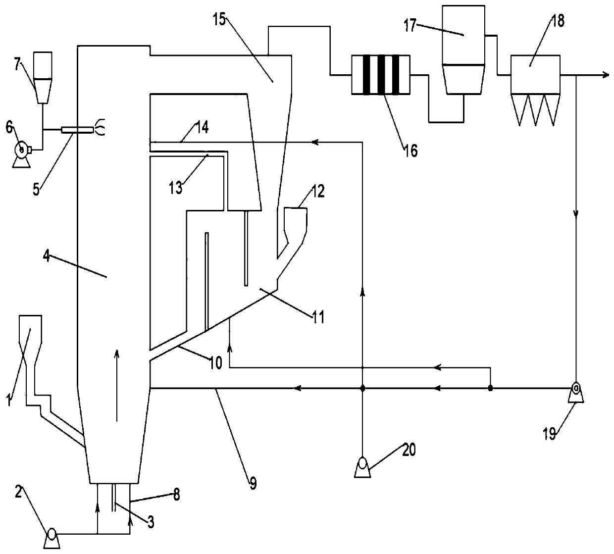
[0044] The bed material at the bottom of the biomass fluidized bed boiler 4 has a static height of 1.2m, and biomass (straw, wood chips) of 20 to 40 meshes is taken as a part of the raw material to enter the biomass fluidized bed boiler 4 from the first feeder 1. Fluidization and combustion under the air supply of 2, the ash obtained during the combustion process is discharged from the slag discharge pipe 3, and the unburned biomass particles and bed materials still carry a large amount of heat, and are separated by the cyclone separator 15 and then enter the return reactor 11 .

[0045] The other part of the biomass raw material enters the feed-back reactor 11 from the second feeder 12, and is gasified by using the heat of the above-mentioned biomass hot particles under the micro positive pressure working condition of 0-5% oxygen concentration and 1-5KPa reaction, the gasified gas (H 2 、C x h y , CO, etc.) enter the denitrification reaction zone of the boiler from the exha...


PUM


Abstract

The invention belongs to the field of biomass fluidized bed combustion and discloses a biomass fluidized bed direct combustion system and a denitration method thereof. The system comprises a biomass fluidized bed boiler, a cyclone separator, a material return reactor, a waste heat boiler, a flue gas purification device and an air distribution device; a first feeder and a slag discharge pipe are arranged at the lower end of the biomass fluidized bed boiler; a denitration device is arranged beside the upper side of the biomass fluidized bed boiler; the cyclone separator is arranged at the upperend of the biomass fluidized bed boiler and is connected with the material return reactor; an exhaust pipe is arranged at the upper end of the material return reactor; a material return pipe is arranged at the lower end of the material return reactor; the exhaust pipe and the material return pipe are both communicated with the biomass fluidized bed boiler; a second feeder is arranged on the material return reactor; one end of the waste heat boiler is connected with the cyclone separator, and the other end of the waste heat boiler is connected with the flue gas purification device; and the airdistribution device is used for supplying air to the biomass fluidized bed boiler. According to the system and method of the invention, the problem of low denitration efficiency in a traditional biomass combustion boiler is solved; high denitration efficiency is realized; and operation cost is reduced.

Description

technical field [0001] The invention belongs to the field of biomass fluidized bed combustion, and more specifically relates to a biomass fluidized bed direct combustion system and a denitrification method thereof. Background technique [0002] In recent years, due to its abundant reserves, low pollution and renewable characteristics, biomass energy has gradually become a research and utilization hotspot. Biomass direct combustion power generation technology has significant advantages such as good fuel adaptability, large production scale, high conversion efficiency, and low pollution emissions. It is the main way to use biomass energy on a large scale at home and abroad. Especially when the quality of biomass fuel fluctuates greatly and the water content is high, and other biomass energy conversion and utilization technologies are difficult to implement, direct combustion utilization has great advantages. [0003] The projects currently included in the catalog of biomass d...

Claims


Application Information

Patent Timeline
Patent Type & Authority Applications(China)
IPC IPC(8): F23C10/26F23J15/02F23L9/00
CPCF23C10/26F23J15/02F23J15/025F23L9/00
Inventor 张世红罗俊伟张雄王信诚刘省标廖新杰向家涛王贤华杨海平陈汉平吴晓松杨文海
Owner HUAZHONG UNIV OF SCI & TECH
Why Eureka
Try Eureka