
Bottom wrapping type vibration hammer profile steel pile pulling machine and pile pulling method thereof

A technology of steel pile pulling machine and vibrating hammer, which is applied in sheet pile wall, construction, infrastructure engineering and other directions, can solve the problems of prolonging the construction period, consuming a certain amount of time, reducing construction efficiency, etc., so as to improve work efficiency and fast sinking speed. , The effect of saving the shift fee

Inactive Publication Date: 2020-04-14
NINGBO HONGCHEN CONSTR
View PDF3 Cites 3 Cited by
  • Summary
  • Abstract
  • Description
  • Claims
  • Application Information

AI Technical Summary

Problems solved by technology

First of all, the construction speed is slow. It takes a certain amount of time for the cutter to rotate and cut off the waste piles under the action of hydraulic pressure, and the long waste piles need to be cut and removed section by section, which further reduces the construction efficiency and prolongs the construction period; moreover, The above-mentioned device is equipped with hydraulically driven cutters, the structure is relatively complex, the cost is high, and its own weight is also relatively large, so it needs to be matched with a large crane; moreover, the above-mentioned double-layer full casing is an integral structure with a fixed height. If the casing is used, the pile frame is too high to be stable, and the bearing capacity of the foundation soil is also required, and the shift fee is also high. If the casing with a small height is selected, the pile extraction depth is insufficient, and it needs to be cut and pulled out in several sections. Affect ergonomics

Method used


Image

  • Bottom wrapping type vibration hammer profile steel pile pulling machine and pile pulling method thereof
  • Bottom wrapping type vibration hammer profile steel pile pulling machine and pile pulling method thereof
  • Bottom wrapping type vibration hammer profile steel pile pulling machine and pile pulling method thereof

Examples


Embodiment Construction

[0030] The present invention will be further described below in conjunction with the accompanying drawings and specific embodiments.

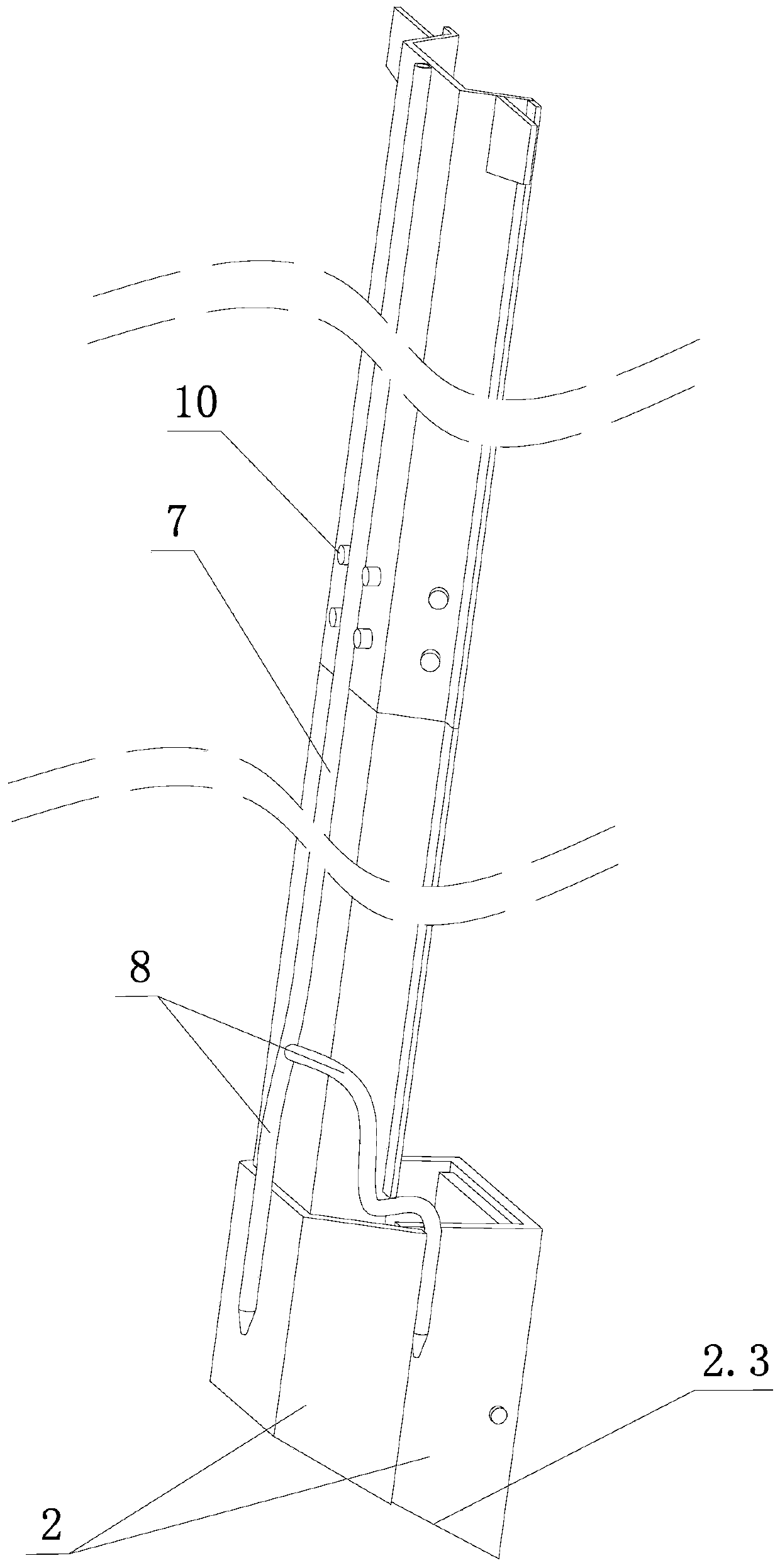
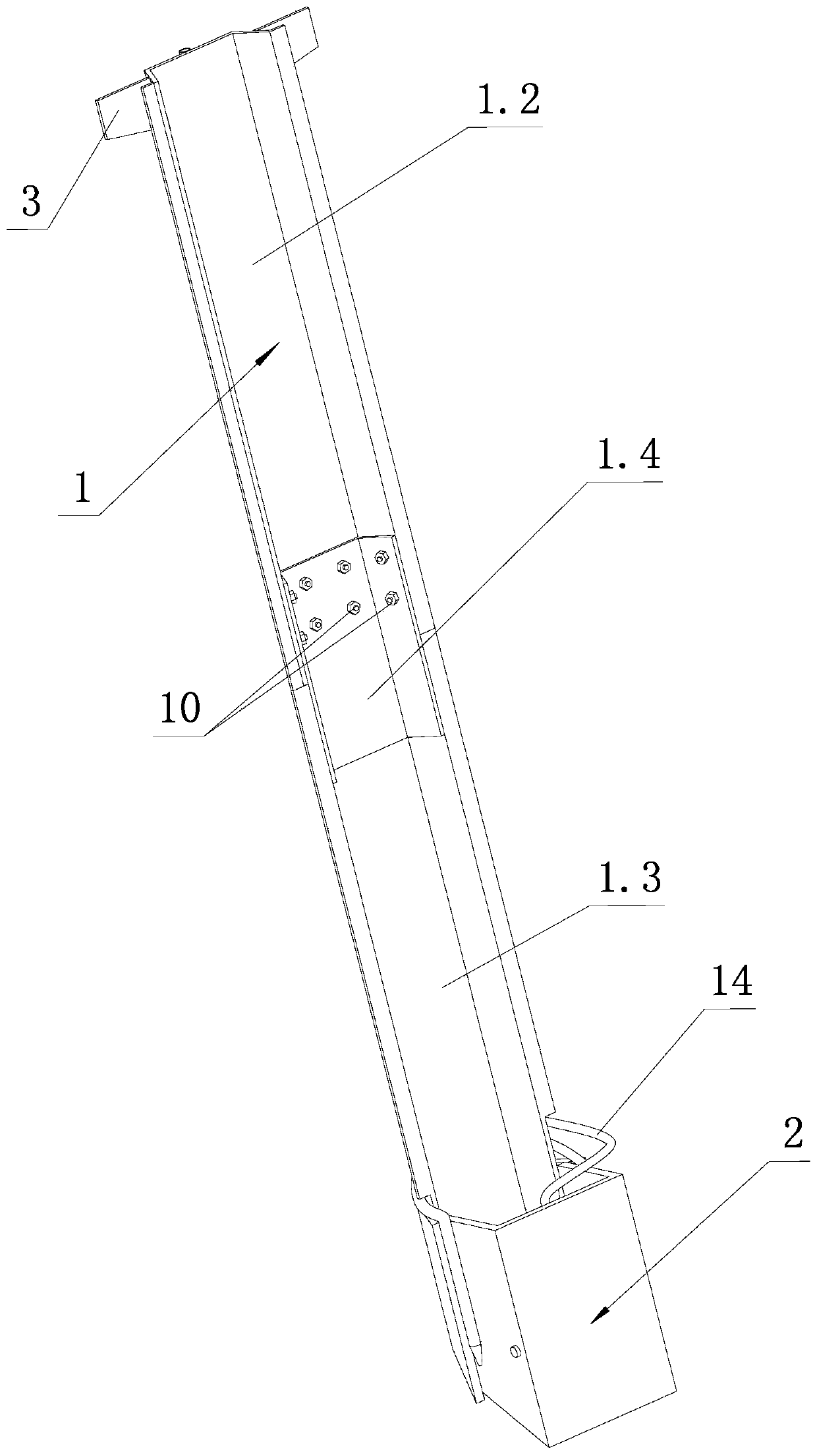
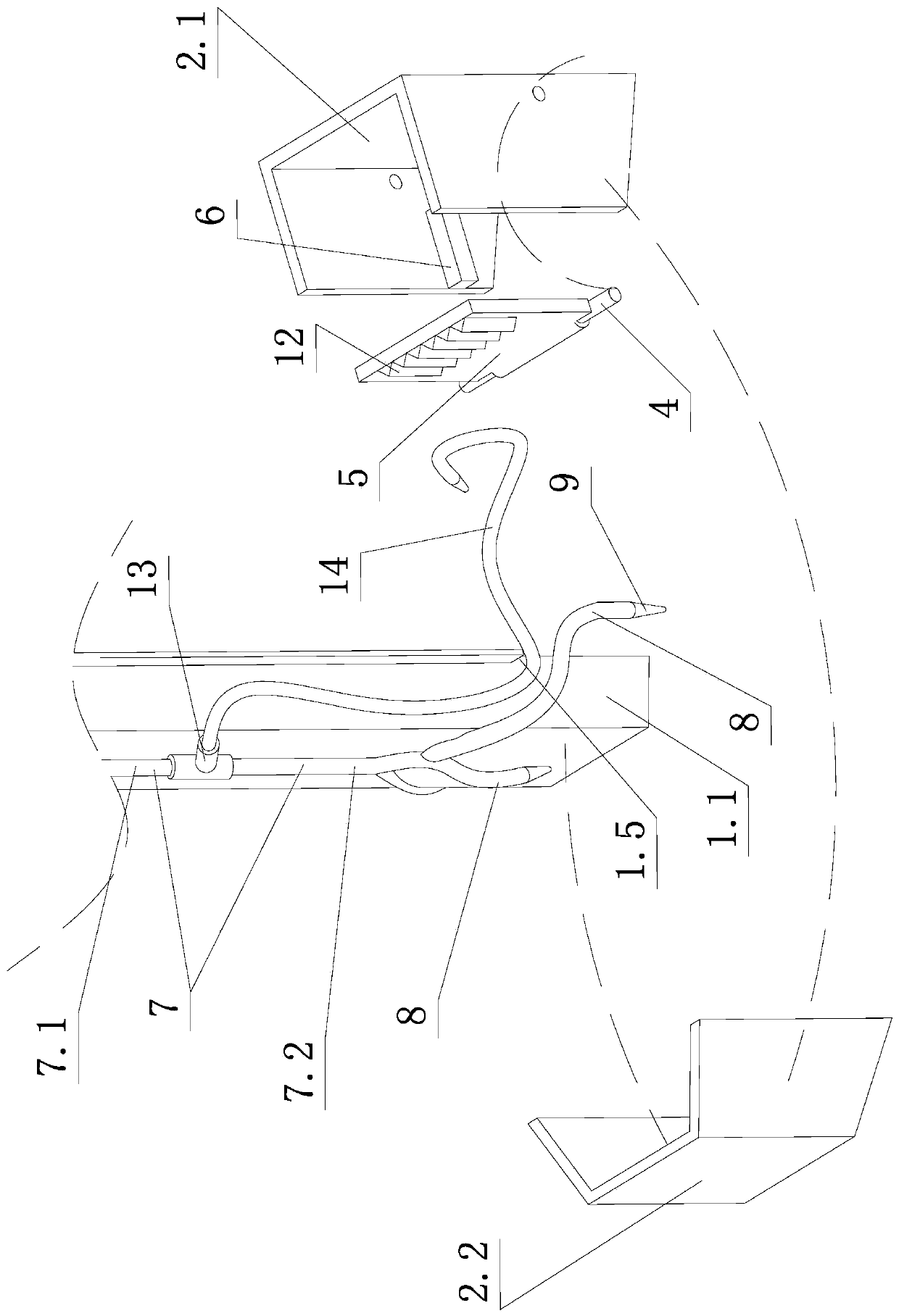
[0031] Such as Figure 1 to Figure 7 Shown, the bottom type vibrating hammer type steel pile extractor of the present invention, it comprises the rod part 1 that is made of Larsen type steel and the pile sleeve 2 that is positioned at the rod part 1 bottom.

[0032] The rod part 1 includes the upper section Larsen type steel 1.2 and the lower section Larsen type steel 1.3, the front side of the lower section Larsen type steel 1.3 is welded with an open connection groove steel plate 1.4, and the open connection groove steel plate 1.4 is connected to the upper section through the bolt 10. Sen type steel 1.2 connection. The opening of the Larsen type steel of the rod part 1 faces forward, and the upper end of the upper section of the Larsen type steel 1.2 of the rod part 1 is welded with an ear plate 3 for connecting a vibratory hammer.

[0033]...


PUM


Abstract

The invention discloses a bottom wrapping type vibration hammer profile steel pile pulling machine and a pile pulling method. The pile pulling machine comprises a Larson type profile steel rod portionand a pile sleeve; standard channel steel and open Larson type channel steel of the pile sleeve are welded in a buckling mode, a rotation shaft is arranged on two flange plates of the standard channel steel and rotatably provided with a bottom wrapping steel plate, limiting blocks are welded to the inner surfaces of the flange plates of the standard channel steel, and the bottom wrapping steel plate is provided with triangular convex strips; and the open Larson type channel steel is welded to the bottom end of the rod portion. The pile pulling machine further comprises a main guide pipe and three branched guide pipes, and the bottom end of each branched guide pipe is provided with a spraying port. The method is characterized in that the pile pulling machine sinks to the bottom of a wastepile at a time, the bottom end of the waste pile is wrapped by the bottom wrapping steel plate, and then the waste pile is pulled out at a time. According to the pile pulling machine and the pile pulling method, the construction speed is high, the efficiency is high, the structure is relatively simple, and the manufacturing cost is low.

Description

technical field [0001] The invention relates to the technical field of pulling out and cleaning waste pile foundations in civil engineering, in particular to a pocket-bottomed vibrating hammer-shaped steel pile puller for pulling out medium and small-diameter (D≤800mm) piles at one time and a pile puller using the pile puller method. Background technique [0002] With the rise of national economic construction and underground space construction, especially in the process of renovating old cities, it is often necessary to pull out the waste pile foundations that remain underground. However, in the prior art, the double-full casing rotary-cut pile cleaning device is mostly used, and the hydraulic cylinder inside the casing is used to drive the tool to protrude inwards to rotate and cut off the waste piles, and then the power head of the pile driver lifts the casing to remove the waste piles. . [0003] There are following defects in the pile clearing device of the above-ment...

Claims


Application Information

Patent Timeline
Patent Type & Authority Applications(China)
IPC IPC(8): E02D9/02
CPCE02D9/02
Inventor 李福连李连方陶灵聪徐和星尚伟
Owner NINGBO HONGCHEN CONSTR
Learn More