A Rapid Repair and Reinforcement Method of Locally Reinforced Embankment
A reinforced embankment and partial technology, applied in roads, roads, buildings, etc., can solve the problems of waste of resources, increase of engineering quantity, etc.
- Summary
- Abstract
- Description
- Claims
- Application Information
AI Technical Summary
Problems solved by technology
Method used
Image
Examples
Embodiment 1
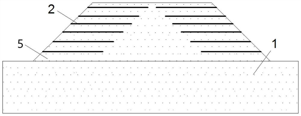
[0057] For the above-mentioned construction method of partially reinforced embankment, familiarize yourself with the design documents before construction, and do a good job of on-site inspection. According to the survey data and design documents, make a timely organizational design, including construction methods, resource allocation, etc., and then carry out basic engineering construction and component production. According to the design and specification requirements, lay the embankment 1, lay the filler and use local materials, which is environmentally friendly and economical. Include the following steps:
[0058] Step A: Treat the subgrade site, level and compact it to meet the design and specification requirements. The embankment 1 is laid with filler, and during the laying process, the filler is laid according to the actual position of the construction line, and the filler is layered and compacted. When the filler is laid, a certain thickness of expansive soil filler is ...
Embodiment 2
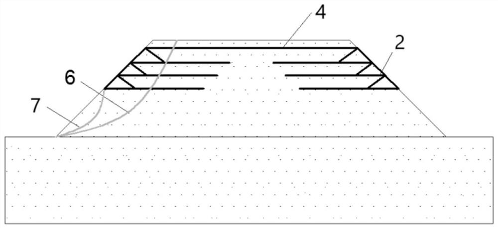
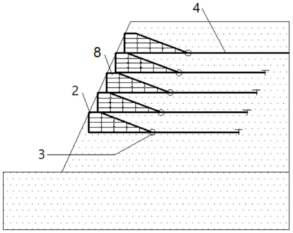
[0064] The above-mentioned rapid repair and reinforcement method for a locally reinforced embankment specifically includes the following steps:
[0065] Step a: Determine the damaged location of the embankment 1, and excavate the slope where sliding failure occurs under the first reinforcement unit 2 at the damaged location according to the damage of the embankment 1, and the depth of the excavation should reach the sliding face position;
[0066] Step b: backfill and compact the excavated side slope layer by layer, and reach a compaction degree that meets the specifications. After the compaction is completed, drill holes perpendicular to the slope of the embankment 1 until the slope Move below the surface;
[0067] Step c: pass the anchor rod 13 through the hole, and the circular top plate 9 end of the anchor rod 13 is placed at the end of the hole drilled in the step b located inside the embankment 1, the anchor rod 13 The center of the circular top plate 9 is provided wit...
PUM
 Abstract
Description
Claims
Application Information
 - R&D
- Intellectual Property
- Life Sciences
- Materials
- Tech Scout
- Unparalleled Data Quality
- Higher Quality Content
- 60% Fewer Hallucinations
Browse by: Latest US Patents, China's latest patents, Technical Efficacy Thesaurus, Application Domain, Technology Topic, Popular Technical Reports.
© 2025 PatSnap. All rights reserved.Legal|Privacy policy|Modern Slavery Act Transparency Statement|Sitemap|About US| Contact US: help@patsnap.com


