Neuron circuit based on memristor

A memristor and neuron technology, applied in the field of neuron devices, can solve the problems of poor real-time response, low misoperation rate, and high misoperation rate, and achieve the effect of reducing error rate and improving real-time performance

Active Publication Date: 2020-04-10
FUDAN UNIV
View PDF9 Cites 7 Cited by
  • Summary
  • Abstract
  • Description
  • Claims
  • Application Information

AI Technical Summary

Problems solved by technology

[0005] The present invention aims to solve the problems of poor real-time response and high misoperation rate in existing neuron circuits, and provide a neuron device with low area cost after integration, good real-time performance and low misoperation rate

Method used


Image

  • Neuron circuit based on memristor
  • Neuron circuit based on memristor
  • Neuron circuit based on memristor

Examples


Embodiment 1

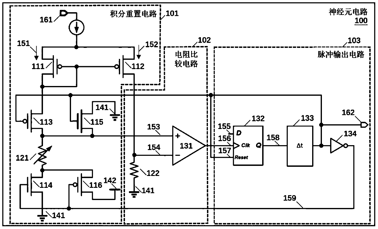
[0032] figure 1 It is the circuit diagram of the first hardware implementation of the memristor-based neuron circuit of the present invention. Such as figure 1 As shown, when the current flows through the memristor 121 from top to bottom, the memristor 121 performs a reset operation, and its resistance value gradually increases; when the current flows through the memristor 121 from bottom to top, the memristor 121 performs a reset operation. operation, its resistance decreases to a low-impedance state. By properly setting the size of the transistors 113 - 116 , the on-resistance of the transistors 113 - 116 can be neglected compared with the resistance value of the low resistance state of the memristor 121 . The input current 161 may be a variable current that flows into the neuron circuit through the sources of transistors 111 and 112 . In the initial state, the output signal 162 is at a low level, the feedback path 159 is at a high level, the transistors 113 and 114 are t...

Embodiment 2

[0037] Figure 5 It is the circuit diagram of the second hardware implementation of the memristor-based neuron circuit of the present invention. The difference from Embodiment 1 mainly lies in the change trend of the memristor 521 and the connection mode of the resistance comparison circuit 531: when the current flows through the memristor 521 from top to bottom, the memristor 521 performs a set operation, and its resistance value gradually increases. decrease; when the current flows through the memristor 521 from bottom to top, the memristor 521 performs a reset operation, and its resistance value rises to a high-impedance state. In the initial state, the output signal 562 is at a low level, the feedback path 559 is at a high level, 513 and 514 are turned on, and the current 551 flows through the memristor 521, making its resistance gradually smaller, and at the same time, the memristor 521 The upper end gets the node 553 voltage. Current 552 flows through transistor 512 th...


PUM


Abstract

The invention belongs to the technical field of neural components, and particularly relates to a neuron circuit based on a memristor. The neuron circuit comprises an integral reset circuit, a resistance comparison circuit and a pulse output circuit, the integral reset circuit takes the current of an external circuit as the input, realizes the integration of the input current through the reset or setting operation of the memristor, and takes the monitoring voltage of the real-time resistance value of the memristor as the output. The resistance comparison circuit receives the real-time monitoring voltage, compares the real-time monitoring voltage with a voltage signal of a reference resistor, and outputs a resistance comparison result to the pulse output circuit; when the real-time monitoring voltage exceeds a threshold value, the pulse output circuit outputs a neural pulse signal to an external circuit and sends a feedback signal to the integral reset circuit, so that the memristor resistance of the integral reset circuit is reset. The method has the advantages of being low in area cost after integration, good in real-time performance and low in misoperation rate.

Description

technical field [0001] The invention belongs to the technical field of neuron devices, and in particular relates to a memristor-based neuron circuit. Background technique [0002] In recent years, driven by Moore's Law, cloud computing and big data, artificial intelligence (AI) technology has made breakthroughs in more and more fields such as speech recognition, image recognition, unmanned driving and medical diagnosis. However, the current large-scale popularization of artificial intelligence technology also faces many problems, such as long training time, high cost of computing resources and labor, and large demand for training data. The development of high-performance computing can alleviate the current problems of artificial intelligence to a certain extent. However, high-performance computing mainly depends on the computing performance of the underlying chip. As the pace of Moore's Law gradually slows down, the shrinking speed of CMOS devices is getting slower and slo...

Claims


Application Information

Patent Timeline
Patent Type & Authority Applications(China)
IPC IPC(8): G06N3/063H03H11/46
CPCH03H11/53G06N3/065Y02D10/00
Inventor 薛晓勇杨何勇赵晨阳姜婧雯田丰实章志元
Owner FUDAN UNIV
Why Eureka
Try Eureka