
DMD-based front oblique image optical system of aperture coding spectral imager

A spectral imager and optical system technology, applied in the field of optics, can solve problems such as the inability to apply in the mid-wave infrared band, and achieve the effects of flexible and fast modulation, cost reduction, and volume reduction

Pending Publication Date: 2020-04-10
XI'AN INST OF OPTICS & FINE MECHANICS - CHINESE ACAD OF SCI
View PDF0 Cites 2 Cited by
  • Summary
  • Abstract
  • Description
  • Claims
  • Application Information

AI Technical Summary

Problems solved by technology

[0005] In order to solve the technical problem that the front-end optical system of the existing DMD-coded aperture-based imaging spectral system cannot be applied in the mid-wave infrared band, the present invention provides a front-end oblique image optical system of a DMD-based aperture-coded spectral imager

Method used


Image

  • DMD-based front oblique image optical system of aperture coding spectral imager
  • DMD-based front oblique image optical system of aperture coding spectral imager
  • DMD-based front oblique image optical system of aperture coding spectral imager

Examples


Embodiment Construction

[0031] The present invention will be further described below in conjunction with accompanying drawing.

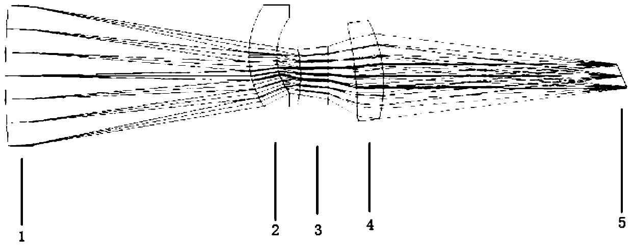
[0032] Such as figure 1 As shown, the front oblique optical system of this embodiment includes a first spherical mirror 1 , a second spherical mirror 2 , a third spherical mirror 3 , a fourth spherical mirror 4 and a DMD encoding device 5 arranged in sequence along the same optical path.

[0033] The first spherical mirror 1 is used as a stop, the second spherical mirror 2 is arranged eccentrically, the first spherical mirror 1 and the third spherical mirror 3 are rotationally symmetrical around the optical axis of the entire front oblique image optical system, and the fourth spherical mirror 4 is eccentric and inclined about the optical axis setting, distant objects are imaged on the inclined DMD encoding device 5 .

[0034] refer to figure 1 , define the sequence number of the mirror surface of each optical element (i.e. the first spherical mirror 1-the fourth spherical...


PUM


Abstract

In order to solve a technical problem of incapability of application of a front optical system of an imaging spectrum system based on DMD coding aperture in a medium-frequency wave infrared waveband,the invention provides a DMD-based front oblique image optical system of an aperture coding spectral imager. The system comprises a first spherical mirror, a second spherical mirror, a third sphericalmirror, a fourth spherical mirror and a DMD coding device which are sequentially arranged along the same optical path. The first spherical mirror is used for limiting the beam size; the first spherical mirror and the third spherical mirror are rotationally symmetrical about the optical axis of the whole front oblique image optical system. One of the second spherical mirror, the third spherical mirror and the fourth spherical mirror is eccentric and obliquely arranged relative to the optical axis. The eccentric size is smaller than or equal to 1 / 4 of the caliber of the front oblique image optical system, and the inclination angle ranges from-24 degrees to 24 degrees; and since the DMD coding device is obliquely arranged, the included angle between the DMD coding device and the optical axisis equal to two times of the working angle of the micromirror.

Description

technical field [0001] The invention relates to the field of optics, in particular to a DMD-based aperture coded spectral imager pre-oblique image optical system. Background technique [0002] Imaging spectroscopy technology has developed rapidly in recent decades, and several techniques have been widely and continuously applied. Imaging spectroscopy systems are mainly divided into optical-mechanical scanning, push-broom and staring imaging according to the imaging method. Compared with the mature structure and relatively fixed technical route of optical-mechanical scanning and push-broom imaging methods, the research of staring imaging spectroscopy technology has no clear constraints on the implementation method, and can support very flexible design. Although there are not many research results with mature structure and superior performance, it is one of the most promising research objects. The staring-type imaging spectroscopy technology using optical filters is the easi...

Claims


Application Information

Patent Timeline
Patent Type & Authority Applications(China)
IPC IPC(8): G01J3/28G01J3/02G02B27/00
CPCG01J3/2823G01J3/0205G02B27/00
Inventor 杨莹
Owner XI'AN INST OF OPTICS & FINE MECHANICS - CHINESE ACAD OF SCI
Learn More