
New energy automobile hub forging device and machining process thereof

A new energy vehicle, wheel forging technology, applied in forging/pressing/hammer devices, wheels, manufacturing tools, etc., can solve problems such as wheel surface damage, and achieve the effect of improving efficiency, saving physical strength and avoiding wear and tear

Active Publication Date: 2020-04-10
SUZHOU QINGZHI NETWORK TECH CO LTD
View PDF8 Cites 2 Cited by
  • Summary
  • Abstract
  • Description
  • Claims
  • Application Information

AI Technical Summary

Problems solved by technology

[0003] In the prior art, during the processing of the wheel hub, the surface of the wheel hub needs to be ground and forged to make the surface of the wheel hub smoother due to the burrs on the surface. The hub is fixed to prevent the hub from being displaced during the processing process. However, in this fixing method, the jig or manipulator is mostly made of metal materials during the fixing process, and friction between the hub and the hub is likely to cause damage to the surface of the hub. Therefore, the new type of the present invention Propose a new energy vehicle hub forging device and its processing technology

Method used


Image

  • New energy automobile hub forging device and machining process thereof
  • New energy automobile hub forging device and machining process thereof
  • New energy automobile hub forging device and machining process thereof

Examples


Embodiment Construction

[0032] In order to make the technical means, creative features, goals and effects achieved by the present invention easy to understand, the present invention will be further described below in conjunction with specific embodiments.

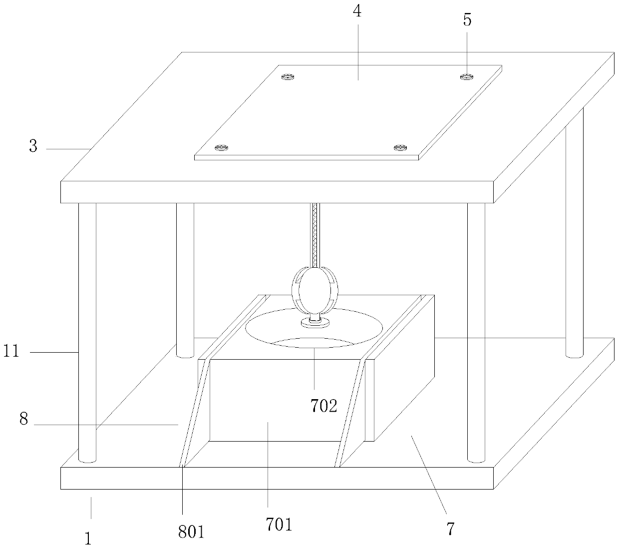
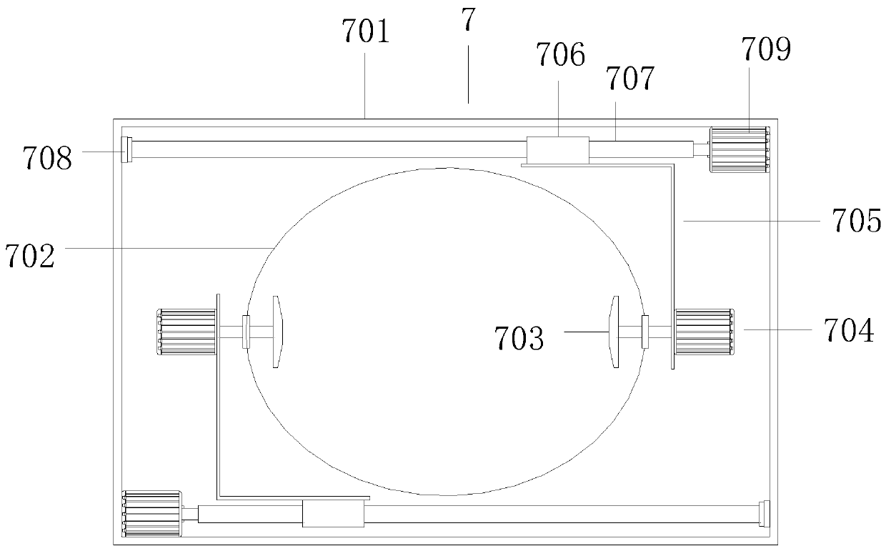
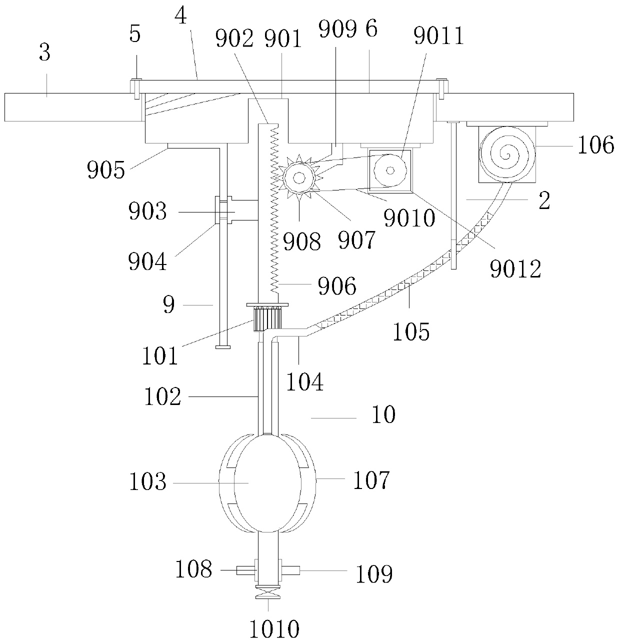
[0033] Such as Figure 1-Figure 7 As shown, a new energy vehicle wheel hub forging device according to the present invention includes a base plate 1, a beam 3 is fixedly connected to the top of the base plate 1 through four support rods 11, and a fixed beam 3 is fixedly connected to the beam 3 through screws 5. plate 4, the fixed plate 4 is fixedly connected with a mounting plate 6, the mounting plate 6 is provided with a moving mechanism 9, and the side of the moving mechanism 9 away from the beam 3 is provided with a fixing mechanism 10, and the beam 3 The lower bottom plate 1 is provided with a processing mechanism 7, and the processing mechanism 7 is provided with a feeding mechanism 8. The design of four support rods 11 can make the whole dev...


PUM


Abstract

The invention relates to the field of hubs, in particular to a new energy automobile hub forging device and a machining process thereof. The forging device comprises a base plate. A cross beam is fixedly connected to the upper portion of the base plate through four supporting rods. A fixed plate is fixedly connected to the cross beam through screws. A mounting plate is fixedly connected to the fixed plate. A moving mechanism is arranged on the mounting plate. A fixing mechanism is arranged on the side, far away from the cross beam, of the moving mechanism. A machining mechanism is arranged inthe position, below the cross beam, of the base plate. The new energy automobile hub forging device is provided with a limiting hook which can prevent an air inlet pipe from being intertwined onto a fixed rod when the fixing mechanism moves downwards. Through arrangement of the fixing mechanism and the moving mechanism, the fixed rod can be driven to move downwards through the moving mechanism andthen be inserted in the middle of a hub. When an airbag is located in the middle of the hub, the airbag is inflated to expand to abut against an inner ring of the hub through clamping cushions. Through the fixing method, the situation that a fixture is used for clamping a hub and the surface of the hub is abraded in the prior art is avoided.

Description

technical field [0001] The invention relates to the field of wheel hubs, in particular to a new energy vehicle wheel hub forging device and a processing technology thereof. Background technique [0002] The hub is a barrel-shaped, center-mounted metal part on the axle that supports the tire inside the tire. Also called rim, steel ring, wheel, tire bell. There are many types of hubs according to diameter, width, molding method and material. [0003] In the prior art, during the processing of the wheel hub, the surface of the wheel hub needs to be ground and forged to make the surface of the wheel hub smoother due to the burrs on the surface. The hub is fixed to prevent the hub from being displaced during the processing process. However, in this fixing method, the jig or manipulator is mostly made of metal materials during the fixing process, and friction between the hub and the hub is likely to cause damage to the surface of the hub. Therefore, the new type of the present i...

Claims


Application Information

Patent Timeline
Patent Type & Authority Applications(China)
IPC IPC(8): B21K1/40B21K27/00B21J9/02B24B9/04B24B41/00B24B41/06B23P15/00B23P23/00
CPCB21J9/02B21K1/40B21K27/00B23P15/00B23P23/00B24B9/04B24B41/005B24B41/06
Inventor 曹元进李婉婉王文昭
Owner SUZHOU QINGZHI NETWORK TECH CO LTD
Learn More