Powder grinding equipment for cosmetics
A technology of cosmetics and powder grinding, which is applied in mechanical equipment, grain processing, springs/shock absorbers, etc. It can solve problems such as single structure and uneven size of grinding powder particles, and achieve the effect of fast driving
- Summary
- Abstract
- Description
- Claims
- Application Information
AI Technical Summary
Problems solved by technology
Method used
Image
Examples
Embodiment 1
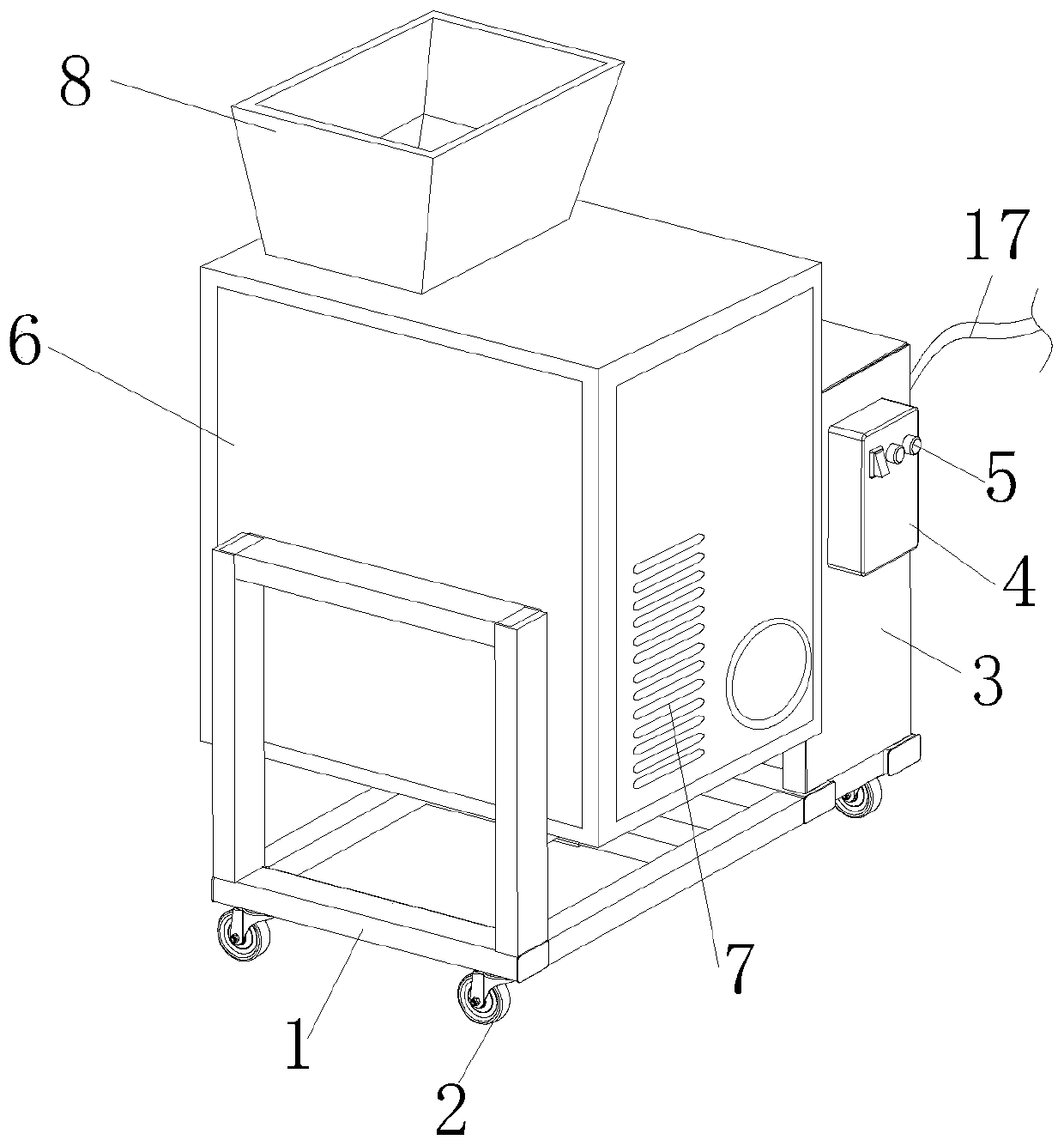
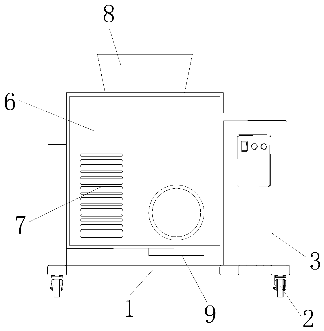
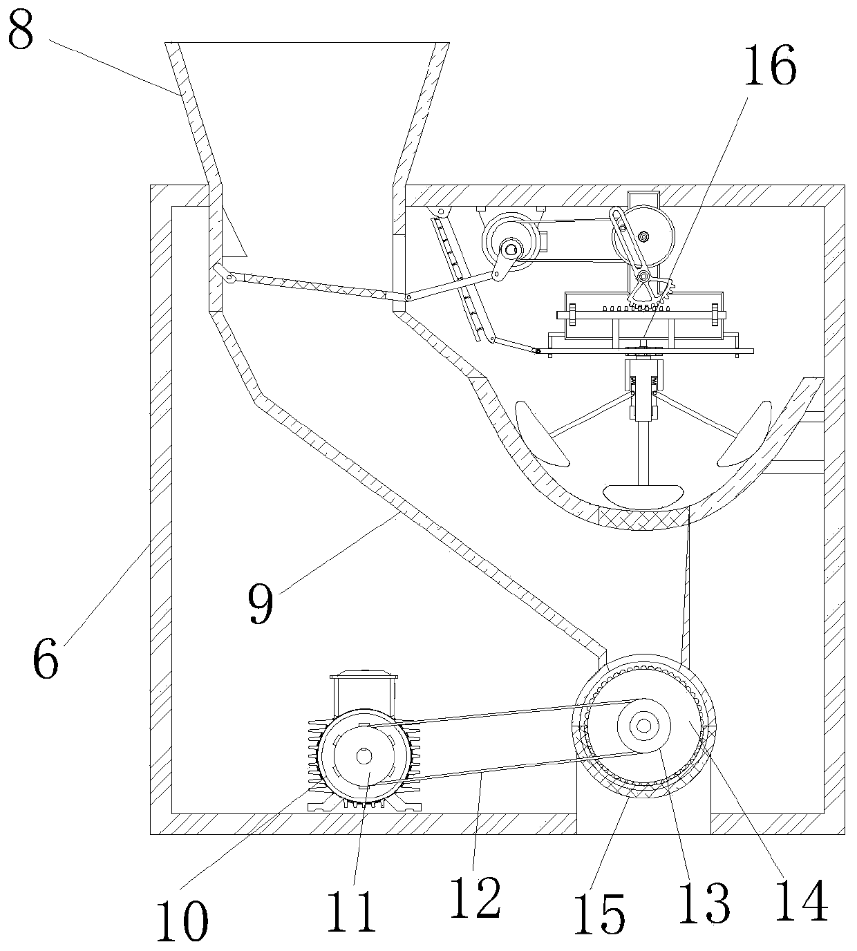
[0037] The present invention provides a kind of powder grinding equipment for cosmetics through improvement, including a fixed frame 1, a powder grinding frame 6, a heat sink 7, a feed hopper 8, a discharge hopper 9, a first motor 10, a powder grinding cylinder 15 and a screening and grinding Device 16, the four corners of the bottom of the fixed frame 1 are oppositely provided with universal wheels 2, the fixed frame 1 and the bottom of the fixed box 3 are fixed as one, the front end of the fixed box 3 is provided with a control panel 4, the front end of the control panel 4 is equipped with a button 5, and the fixed frame 1 The front and rear sides of the milling frame 6 are closely fixed by electric welding, and the right end and lower left side of the fixed frame 1 are equidistantly provided with cooling grooves 7. The screening and grinding device 16 is installed at the upper right end inside the milling frame 6. Swing mechanism 162, preliminary grinding mechanism 163 and b...
Embodiment 2
[0049] The present invention provides a kind of powder milling equipment for cosmetics through improvement. The upper left end inside the feeding hopper 8 is provided with a deflector block 81, and the deflector block 81 is fixed to the upper left end inside the feeding hopper 8 by electric welding. The sliding chamber 16431 is equidistantly distributed on the left end of the inclined plate 1643, and the buffer spring 16310 is fixed to the inner side of the sliding chamber 16431, and the inner side of the upper end of the swing rod 1624 is provided with a sliding groove 16241, and the protruding shaft 1623 slides and fits along the inner side of the sliding groove 16241 The right end of the movable rod 1642 is provided with a connecting groove 16421, and the push shaft 1641 is slidably connected with the inner side of the connecting groove 16421. There are two sliding blocks 1639, and the upper ends of the sliding blocks 1639 are provided with connecting rollers 1634, first Gri...
PUM
 Abstract
Description
Claims
Application Information
 - Generate Ideas
- Intellectual Property
- Life Sciences
- Materials
- Tech Scout
- Unparalleled Data Quality
- Higher Quality Content
- 60% Fewer Hallucinations
Browse by: Latest US Patents, China's latest patents, Technical Efficacy Thesaurus, Application Domain, Technology Topic, Popular Technical Reports.
© 2025 PatSnap. All rights reserved.Legal|Privacy policy|Modern Slavery Act Transparency Statement|Sitemap|About US| Contact US: help@patsnap.com


