
Automatic fuel cell stacking system

A technology of fuel cells and electric stacks, applied in the field of fuel cell automatic stacking systems, which can solve problems such as difficult to control the balance of fastening, damage to proton exchange membrane fuel cells, and increased contact resistance

Pending Publication Date: 2020-04-03
魔方氢能源科技(江苏)有限公司
View PDF12 Cites 9 Cited by
  • Summary
  • Abstract
  • Description
  • Claims
  • Application Information

AI Technical Summary

Problems solved by technology

However, when the nut is locked, the locking sequence is completed independently, resulting in a sequence of locking and differences in locking. It is difficult to control the balance of the final tightening, resulting in the uneven pressure on the top and bottom of the end plate, and the bipolar plate and membrane inside the stack. It is also difficult to balance the direct mutual pressure of the electrodes; and there are processing errors in raw materials such as bipolar plates, and the processing errors will accumulate during final assembly, which will increase the unevenness of the force inside the stack.
When the contact pressure in some areas inside the stack is too high, it is easy to deform the bipolar plate, and the proton exchange membrane fuel cell produced by it will also fail and damage; when the contact pressure in some areas inside the stack is too small, the bipolar plate and other components There will be gaps between them, and the seal of the fuel cell is not firm, which will cause hydrogen and oxygen to cross each other. In addition, the contact resistance between the membrane electrode and the bipolar plate will also increase sharply, and the internal resistance of the battery will increase, which will eventually affect the performance of the entire fuel cell.

Method used


Image

  • Automatic fuel cell stacking system
  • Automatic fuel cell stacking system
  • Automatic fuel cell stacking system

Examples


Embodiment Construction

[0028] The following are specific embodiments of the present invention and in conjunction with the accompanying drawings, the technical solutions of the present invention are further described, but the present invention is not limited to these embodiments.

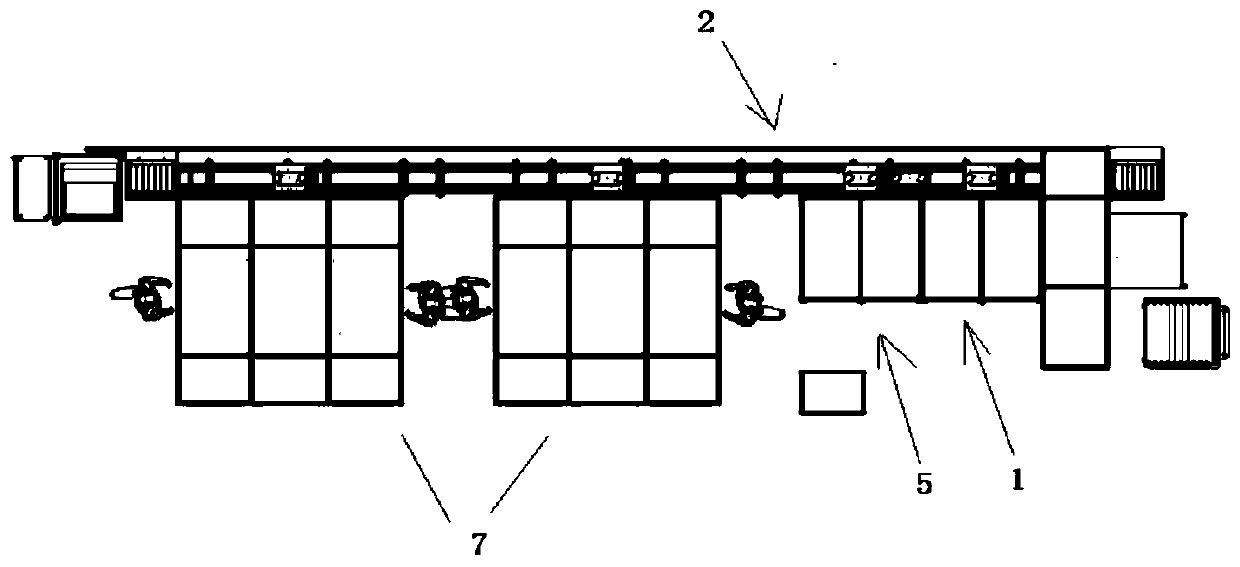
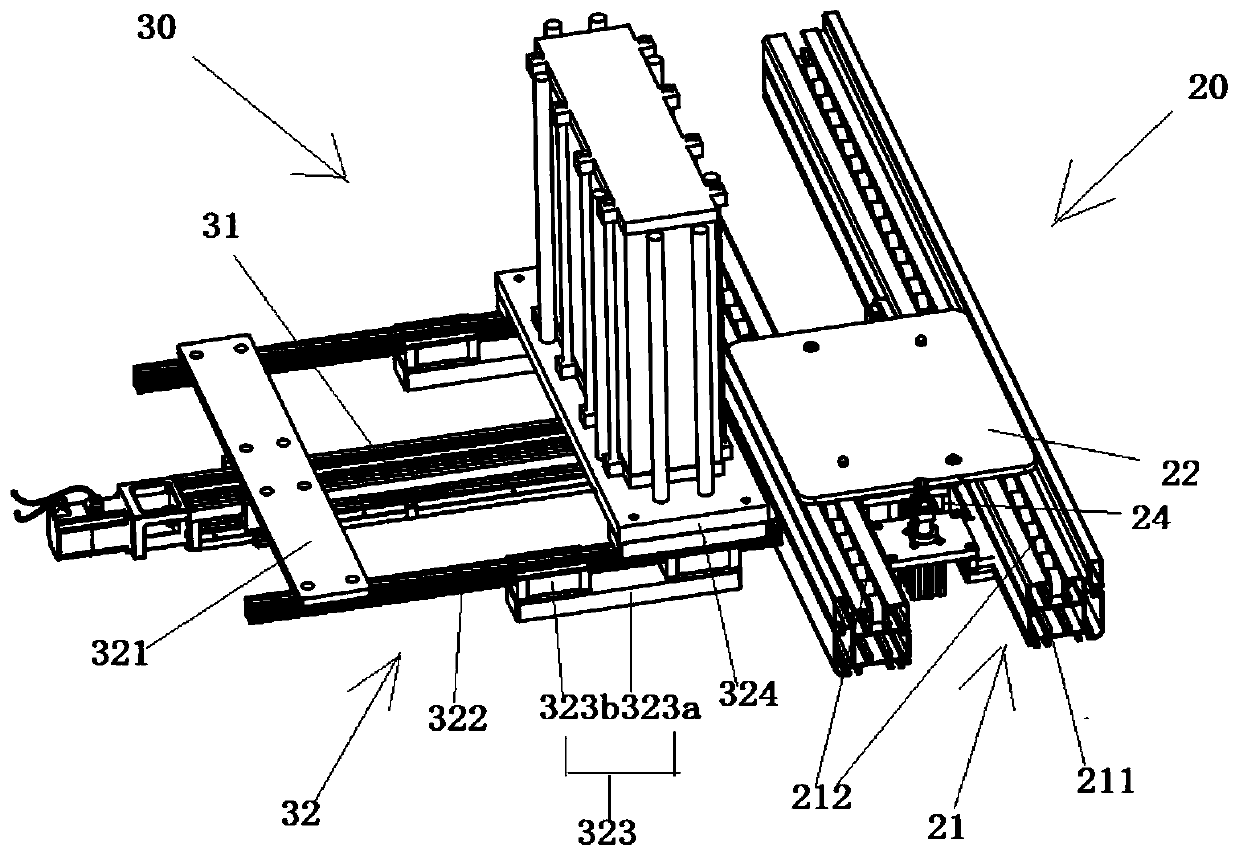
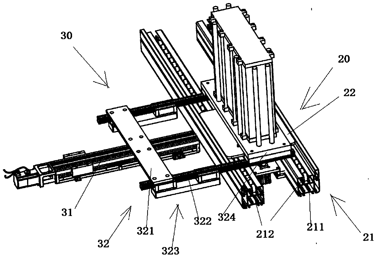
[0029] Such as figure 1 As shown, an automatic fuel cell stacking system of the present invention includes a transfer and conveying device 2, a stack assembly device 7, a press-fit locking device 5 and a detection device 1; the stack assembly device 7 is used to stack electrodes The plates are stacked to form a stack assembly module 11, the press-fit locking device 5 is used to press-fit and lock the stack assembly module 11, and the detection device 1 is used to test the airtightness and insulation of the stack assembly module 11; The loading and conveying device 2 includes a conveying mechanism 20 and a plurality of transfer mechanisms 30. The cell stack stacking device 7, the press-fit locking device 5 and the detection...


PUM


Abstract

The invention discloses an automatic fuel cell stacking system. The system comprises a transferring and conveying device, an electric pile stacking device, a press fitting and locking device and a detection device, wherein the electric pile stacking device is used for stacking electrode plates into an electric pile assembly module, the press fitting and locking device is used for carrying out press fitting and locking on the electric pile assembly module, and the detection device is used for carrying out air tightness and insulation detection on the electric pile assembly module; the transferring and conveying device comprises a conveying mechanism and a plurality of transferring mechanisms. The electric pile stacking device, the press fitting and locking device and the detection device are sequentially arranged at intervals in the conveying direction of the conveying mechanism; the plurality of transferring mechanisms are respectively arranged in one-to-one correspondence with the electric pile stacking device, the press fitting and locking device and the detection device; and the electric pile assembly module is transferred between the conveying mechanism and the electric pile stacking device and between the press fitting and locking device and the detection device. High-precision automatic assembly of the fuel cell stack is realized, and the stack efficiency of the fuel cellstack is greatly improved.

Description

technical field [0001] The invention relates to the technical field of proton exchange membrane fuel cells, in particular to an automatic stacking system for fuel cells. Background technique [0002] The proton exchange membrane fuel cell is composed of multiple single cells stacked in series, fastened by internal positioning screws or clips. Composition of fuel cell stacks. When the stack is working, hydrogen and oxygen enter from the inlet respectively, and are distributed to the bipolar plates of each single cell through the main channel of the stack. When stacking, it is necessary to ensure that the plates are pressed against each other to prevent gas leakage, and ensure that the main gas channels of each plate are aligned so that hydrogen and oxygen can reach each single cell of the fuel cell smoothly. The stacking quality of the fuel cell is closely related to the performance of the battery product. If there is no good positioning device for each single cell during a...

Claims


Application Information

Patent Timeline
IPC IPC(8): H01M8/2404H01M8/247H01M8/249
CPCH01M8/2404H01M8/247H01M8/249Y02E60/50
Inventor 华周发谢飞胡强殷龙
Owner 魔方氢能源科技(江苏)有限公司
Learn More