
A test device for marine diesel engine

A marine diesel engine and test device technology, which is applied in the field of marine diesel engine test devices and marine diesel engine test benches, can solve the problems of limited gasket thickness specifications, vibration and noise, and broken mounting feet, and achieve reliable screw loosening and elimination. The effect of clearance, reliable support

Active Publication Date: 2021-09-21
JIANGSU UNIV OF SCI & TECH
View PDF6 Cites 0 Cited by
  • Summary
  • Abstract
  • Description
  • Claims
  • Application Information

AI Technical Summary

Problems solved by technology

As we all know, the diesel engine has four independent rigid mounting feet, which are rigidly connected with the diesel engine. In theory, in the height direction, the height of the bottom plane of each mounting foot to the centerline of the crankshaft of the diesel engine is the same, that is, the four mounting feet The bottom plane of the feet is theoretically on the same plane. In fact, due to manufacturing errors, positioning errors, assembly errors, etc., the bottom planes of the four mounting feet are not a plane, but there is a slight error, although it does not affect the diesel engine and the load device. connection accuracy, but the diesel engine usually has only three mounting feet supported on the fixed support, and the other foot is suspended in the air, thus causing the center of gravity of the diesel engine to be unstable. During the test run of the diesel engine, vibration and noise will be generated. In severe cases, it will cause The mounting feet are broken. In order to ensure that the four mounting feet of the diesel engine can be effectively supported at the same time, gaskets are usually added under the suspended mounting feet. Since the mounting feet of each diesel engine have different suspended heights and the thickness of the gasket is limited, therefore, This method is difficult to completely eliminate the gap between the mounting feet and the fixed support, so it cannot completely overcome the vibration and noise caused by the installation of the diesel engine

Method used


Image

  • A test device for marine diesel engine
  • A test device for marine diesel engine
  • A test device for marine diesel engine

Examples


Embodiment Construction

[0026] In order to make the purpose of the present invention and technical scheme statement clearer, the present invention will be further described below in conjunction with accompanying drawing and embodiment:

[0027] Those skilled in the art can understand that, unless otherwise defined, all terms (including technical terms and scientific terms) used herein have the same meaning as commonly understood by those of ordinary skill in the art to which this invention belongs.

[0028] The meaning of "left, right, up, down, front, back" mentioned in the present invention means that when the reader is facing the drawings, the left side of the reader is left, the right side of the reader is right, and the reader's right side is right. The upper edge of the reader is the upper edge, the lower edge of the reader is the lower edge, the face in the paper in front of the reader is the front, and the face facing the reader is the back, rather than specific limitations to the present inve...


PUM


Abstract

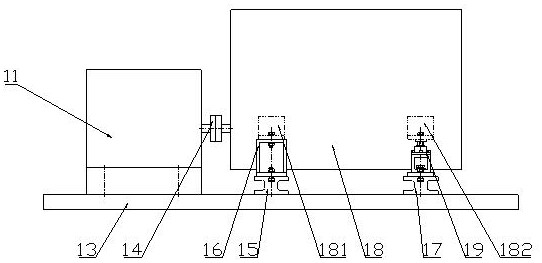
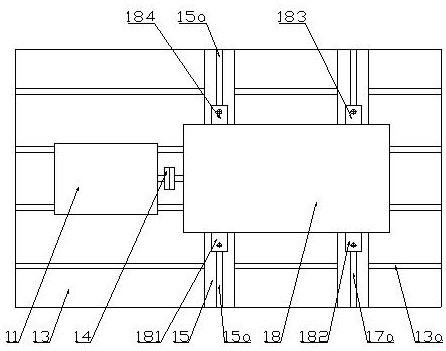
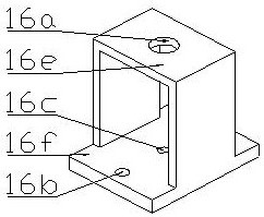
A test device for a marine diesel engine lies in its bench structure, which includes a base on which a load device and a horizontal parallel iron are arranged; the horizontal parallel iron is provided with three fixed supports and one adjustable support, And corresponding to the four mounting feet of the diesel engine; the adjustment support, from top to bottom, is arranged in sequence: bowl-shaped gasket, screw sleeve, fixing nut, nut seat, positioning pin, fixing plate; the screw The inner thread of the sleeve is right-handed, the outer thread is left-handed, and the pitch of the inner thread and the outer thread is the same; the screw sleeve, its left-handed outer thread is connected with the fixing nut; the fixing nut is fixedly connected on the nut seat; the nut seat Fixedly connected on the fixed plate; the fixed plate is fixedly connected with the horizontal shim; the present invention utilizes the adjustment and support function of the adjustment support to meet the requirements of the diesel engine installation, and the four installation feet can be effectively supported. At the same time, the adjustment support The left and right-handed threads set inside and outside the screw sleeve can effectively prevent the mounting screws from loosening.

Description

technical field [0001] The invention relates to a test device for a marine diesel engine, in particular to a test bench for a marine diesel engine, and belongs to the technical field of diesel engine production technology. Background technique [0002] Before leaving the factory, marine diesel engines need to be run-in, debugged and other test items. Therefore, it is necessary to install the diesel engine on the test bench. The test bench is usually on a base with a longitudinal T-shaped slot, and through T-shaped bolts, two transverse pad irons and a load device are respectively fixed. There is a fixed support on the iron. Before the diesel engine is tested, the diesel engine and the load device are elastically connected through an elastic coupling, and then the mounting feet of the diesel engine are connected to the fixed support with screws. As we all know, the diesel engine has four independent rigid mounting feet, which are rigidly connected with the diesel engine. In ...

Claims


Application Information

Patent Timeline
Patent Type & Authority Patents(China)
IPC IPC(8): G01M15/04G01M15/02
CPCG01M15/02G01M15/04
Inventor 孙安龙梁忠臣笪月君
Owner JIANGSU UNIV OF SCI & TECH
Learn More