Self-centering floating drive

A driving device and self-centering technology, applied in the accessories of tool holders, tailstock/top, metal processing equipment, etc., can solve the problems of large clamping accuracy deviation, low clamping reliability, poor controllability, etc. The effect of reducing failure rate, reducing bump and clamping time, and reasonable structure

Active Publication Date: 2022-08-09
ZHEJIANG WEIKE MACHINERY TECH
View PDF9 Cites 0 Cited by
  • Summary
  • Abstract
  • Description
  • Claims
  • Application Information

AI Technical Summary

Problems solved by technology

[0009] The present invention provides a self-centering floating driving device, which overcomes the deficiencies of the prior art and effectively solves the problems of large clamping accuracy deviation, over-positioning and poor stability in the existing clamps
[0010] The present invention further solves the problems of poor controllability and low clamping reliability

Method used


Image

  • Self-centering floating drive
  • Self-centering floating drive
  • Self-centering floating drive

Examples


Embodiment Construction

[0040] The present invention is not limited by the following examples, and specific implementations can be determined according to the technical solutions and actual conditions of the present invention.

[0041] In the present invention, for the convenience of description, the description of the relative positional relationship of each component is based on the appendix of the description. figure 1 For example, the positional relationship of front, rear, top, bottom, left and right is determined according to the layout direction of the drawings in the description.

[0042] Below in conjunction with embodiment and accompanying drawing, the present invention is further described:

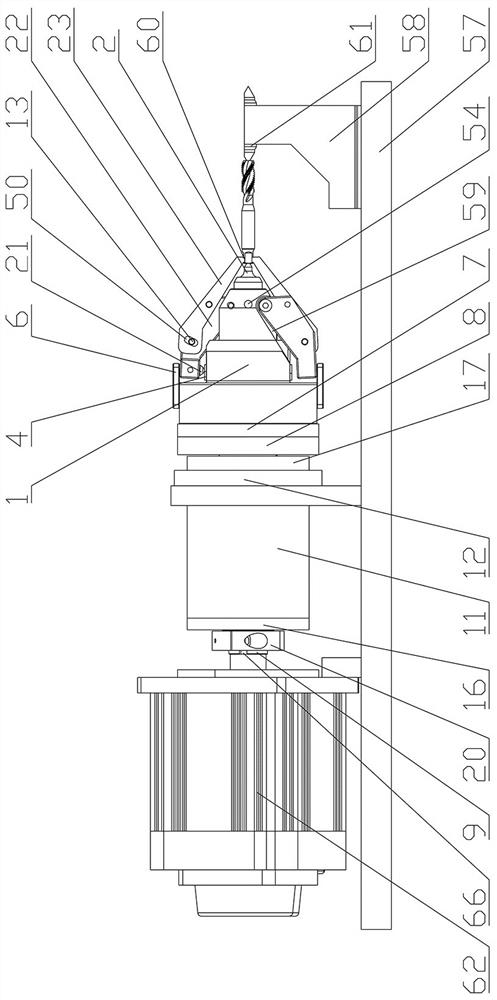
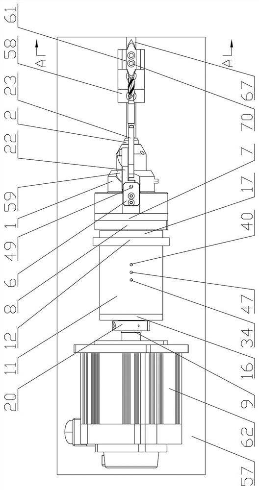
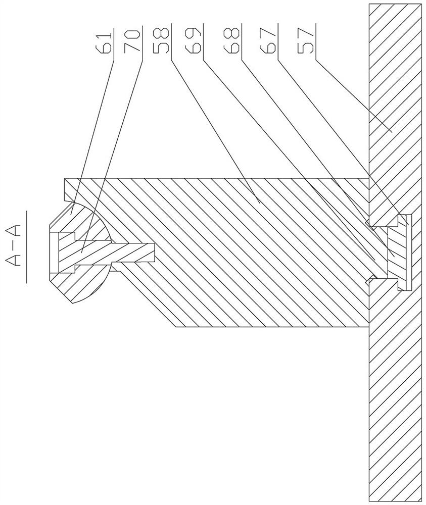
[0043] as attached Figures 1 to 15 As shown, the self-centering floating driving device includes a chuck body 1, a top 2, a jaw assembly, a main piston 3, a secondary piston 4, a base 57, a tailstock 58 and a driving device. The chuck body 1 is arranged above the base 57. , the left end of the chuc...


PUM


Abstract

The invention relates to the technical field of clamps, and is a self-centering floating driving device, comprising a chuck body, a top, a clamping claw assembly, a main piston, a sub-piston, a base, a tailstock and a driving device. The structure of the invention is reasonable and compact, the driving device drives the main piston to move to the left, and one end of the workpiece to be processed is placed against the right end of the center, the center plays the role of centering the workpiece to be processed, and then the main piston moves to the right. The jaws are hingedly connected to the outside of the chuck body, so the jaws can float according to the specifications of the workpiece to be processed during the clamping process, and finally clamp the workpiece to be processed under the action of the reset shrapnel, which can automatically adjust the clamping position to avoid The over-positioning of the claws realizes high-precision clamping and positioning, and the limit groove can prevent the connecting plate from shifting during the rotation of the chuck body, enhance the stability of the present invention in use, and has the advantages of small clamping accuracy deviation, Multi-process one-time clamping, accurate positioning, stability and high efficiency.

Description

technical field [0001] The invention relates to the technical field of clamps, and is a self-centering floating drive device. Background technique [0002] Gripper is one of the important process equipments in the traditional machinery manufacturing industry. Its application has been expanded horizontally to various production fields such as inspection, welding and assembly automation after the 1980s, and has greater development prospects. [0003] In the production of automated assembly equipment, grippers are usually used to assist production, such as the positioning of the outer cylinder, spring and gasket of the airtight cylinder. Generally speaking, the outer cylinder, spring and gasket of the airtight cylinder are made of The pallets are transported to the assembly station on double-speed chains. During assembly, the gaskets and springs on the tray need to be placed in the cylinder of the outer cylinder one by one. Since the springs and gaskets are manually placed on ...

Claims


Application Information

Patent Timeline
Patent Type & Authority Patents(China)
IPC IPC(8): B23B31/02B23B31/10B23B31/103B23B23/00B24B41/06
CPCB23B31/02B23B31/102B23B31/103B23B23/005B24B41/062
Inventor 王宏波李文磊张剑
Owner ZHEJIANG WEIKE MACHINERY TECH
Why Eureka
Try Eureka