
Molding and preparation method of carbon fiber transmission shaft for Formula Student racing car

A technology for Formula Student and transmission shafts, which is applied in the field of forming and preparation of carbon fiber transmission shafts for Formula Student racing cars. It can solve the problems of unstable quality, corrosion resistance, and unstable connection between the carbon fiber shaft body and the metal connection end, and achieve The effect of small moment of inertia, improved transmission performance and high connection strength

Active Publication Date: 2020-06-19
WUHAN UNIV OF TECH
View PDF7 Cites 0 Cited by
  • Summary
  • Abstract
  • Description
  • Claims
  • Application Information

AI Technical Summary

Problems solved by technology

[0003] The invention provides a method for forming and preparing a carbon fiber transmission shaft for a Formula Student racing car, the purpose of which is to overcome the defect that the traditional carbon fiber shaft body and the metal connection end are not firmly bonded and the quality and corrosion resistance of the traditional steel transmission shaft of a Formula Student racing car performance deficiencies
Provides a "double lap-mechanical connection" hybrid connection method to connect the carbon fiber transmission shaft body and the metal joint, which solves the existing problem of unstable connection; at the same time, the carbon fiber transmission shaft is light in weight and has a small moment of inertia. The characteristics of high natural frequency make up for the deficiency of the traditional steel drive shaft, and greatly improve the transmission performance of the car

Method used


Image

  • Molding and preparation method of carbon fiber transmission shaft for Formula Student racing car
  • Molding and preparation method of carbon fiber transmission shaft for Formula Student racing car
  • Molding and preparation method of carbon fiber transmission shaft for Formula Student racing car

Examples


Embodiment Construction

[0046] Below in conjunction with embodiment and attached Figure 1-12 The present invention is described in detail.

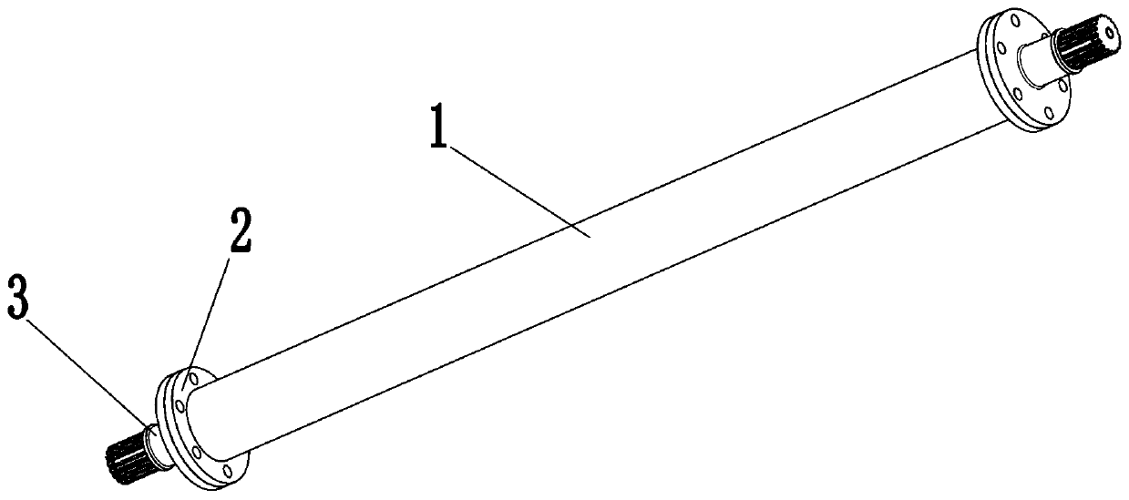
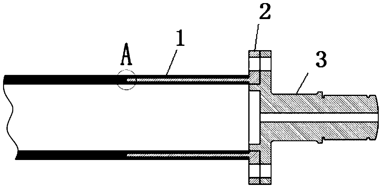
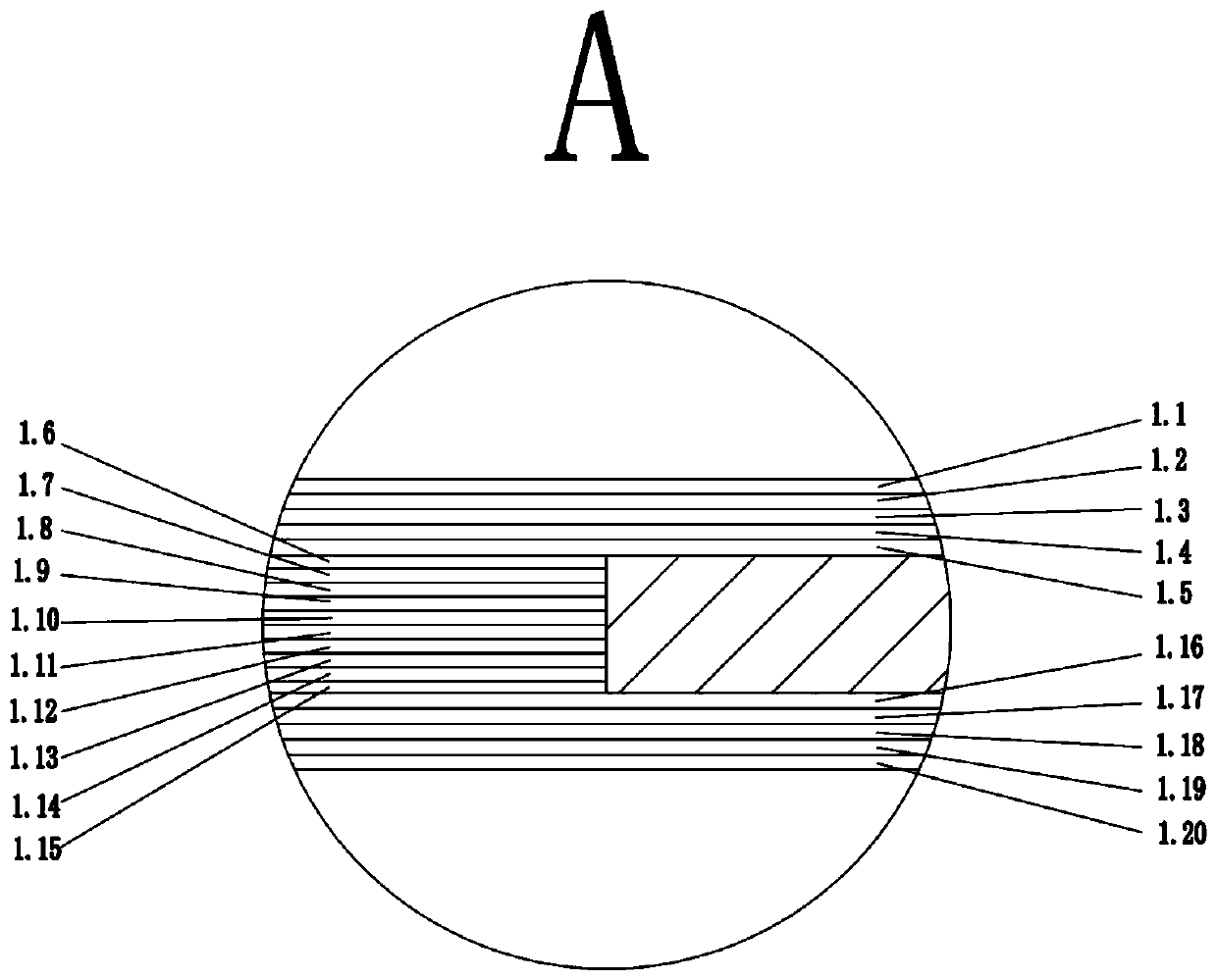
[0047] figure 1 The shown carbon fiber transmission shaft for a Formula Student racing car includes a carbon fiber transmission shaft body 1 , a metal connection end 2 and a spline end 3 . The shaft body 1 of the carbon fiber transmission shaft is hollow, and it is mainly divided into three stages of lamination. Figure 4 The metal connection end 2 shown is in the shape of a sleeve of a rotary body. The metal connection end 2 is divided into two parts, one part is the flange end 2.1, and the other part is the glue connection end 2.2. 6 holes 2.5 of M6 have a hole 2.6 with a diameter of 30mm in the central part. Figure 8 The spline end 3 shown is divided into two parts, one part is the spline 3.3 designed according to the three-ball pin, and the other side is the flange 3.1 matched with the metal connection end, and there are 6 M6 evenly distributed on the e...


PUM

PropertyMeasurementUnit
lengthaaaaaaaaaa
thicknessaaaaaaaaaa
thicknessaaaaaaaaaa

Abstract

The invention relates to a method for forming and preparing a carbon fiber drive shaft for a college students' formula car. Carbon fiber prepregs are used for winding a mandrel, after the mandrel is connected with connecting ends, winding is preformed continuously. The mandrel is removed by solidification after winding, spline ends are connected to form an integral shaft, a carbon fiber shaft bodyis formed by symmetrical angle layering in three stages, the metal connection ends are divided into flange edges and internal and external gluing parts, the spline ends are divided into flange edgesand spline parts, and the carbon fiber shaft body and the metal connection ends are in a double-lapped connection and mechanical connection mode, and the metal connection ends and the spline ends arefixed by bolts passing through the holes of the flange edges. The drive shaft can be used for various purposes by replacing the spline ends, has high durability and high fiber content, the connectionstrength between the metal connection end and the carbon fiber shaft body is high, the mass of the drive shaft is low, the rotational inertia is small and the natural frequency is high.

Description

technical field [0001] The invention belongs to the fields of composite materials and traditional mechanical processing, and specifically relates to a forming process of carbon fiber shaft-shaped products and a mechanical processing process of revolving parts, and specifically refers to a forming and preparation process of a carbon fiber transmission shaft for Formula Student racing cars. Background technique [0002] Carbon fiber is a special fiber composed of carbon elements, which has the characteristics of general carbon materials such as abrasion resistance, electrical conductivity, and thermal conductivity, and also has the characteristics of anisotropy. It has lower density than metal aluminum, higher specific weight, higher specific strength of steel resistance, better mold corrosion resistance and better fatigue resistance. During the collision, the energy absorption capacity of carbon fiber composite materials is 5-6 times that of steel. Due to its superior perfor...

Claims


Application Information

Patent Timeline
Patent Type & Authority Patents(China)
IPC IPC(8): B29C70/34B29C70/54B29C70/76
CPCB29C70/34B29C70/54B29C70/76
Inventor 徐峰祥唐跃友罗宇彤袁金呈邵建波
Owner WUHAN UNIV OF TECH
Learn More