
Working method of punching device with protective structure and for bridge construction

A protective structure and drilling device technology, which is applied in the direction of working accessories, manufacturing tools, stone processing tools, etc., can solve the problems of inconvenient adjustment of drilling diameter and hazards to construction personnel, so as to prevent hazards, enhance protection, and enhance flexibility Effect

Active Publication Date: 2020-04-03
安徽启源建筑工程有限公司
View PDF5 Cites 3 Cited by
  • Summary
  • Abstract
  • Description
  • Claims
  • Application Information

AI Technical Summary

Problems solved by technology

[0006] The purpose of the present invention is to provide a drilling device with a protective structure for bridge construction, to solve the problem that the current drilling device for bridge construction proposed in the above-mentioned background technology uses a drill bit for drilling and the waste chips produced are easy to cause trouble for construction personnel. Hazards, and the problem of inconvenient adjustment of drilling diameter

Method used


Image

  • Working method of punching device with protective structure and for bridge construction
  • Working method of punching device with protective structure and for bridge construction
  • Working method of punching device with protective structure and for bridge construction

Examples


Embodiment Construction

[0022] The following will clearly and completely describe the technical solutions in the embodiments of the present invention with reference to the accompanying drawings in the embodiments of the present invention. Obviously, the described embodiments are only some, not all, embodiments of the present invention. Based on the embodiments of the present invention, all other embodiments obtained by persons of ordinary skill in the art without making creative efforts belong to the protection scope of the present invention.

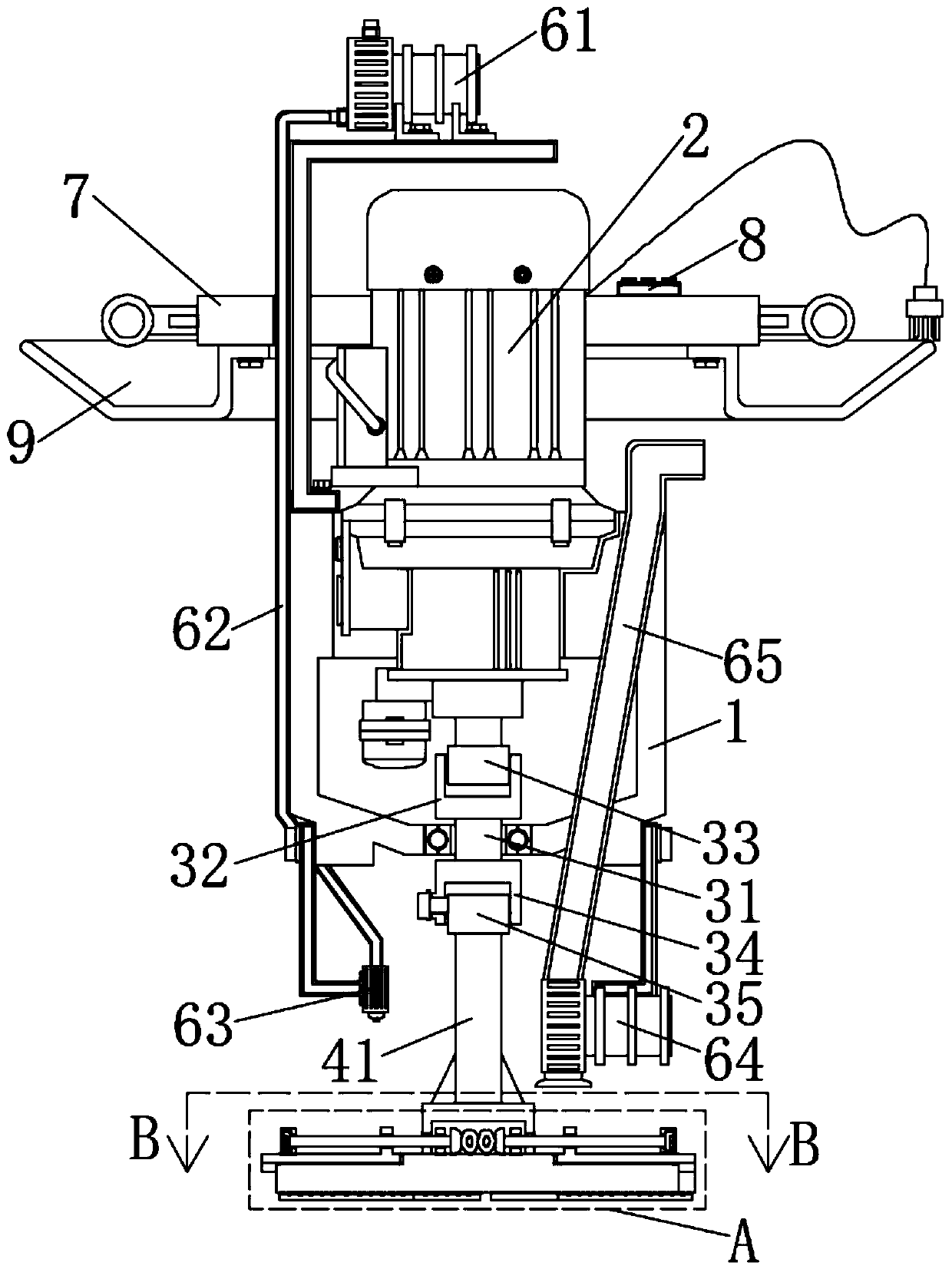
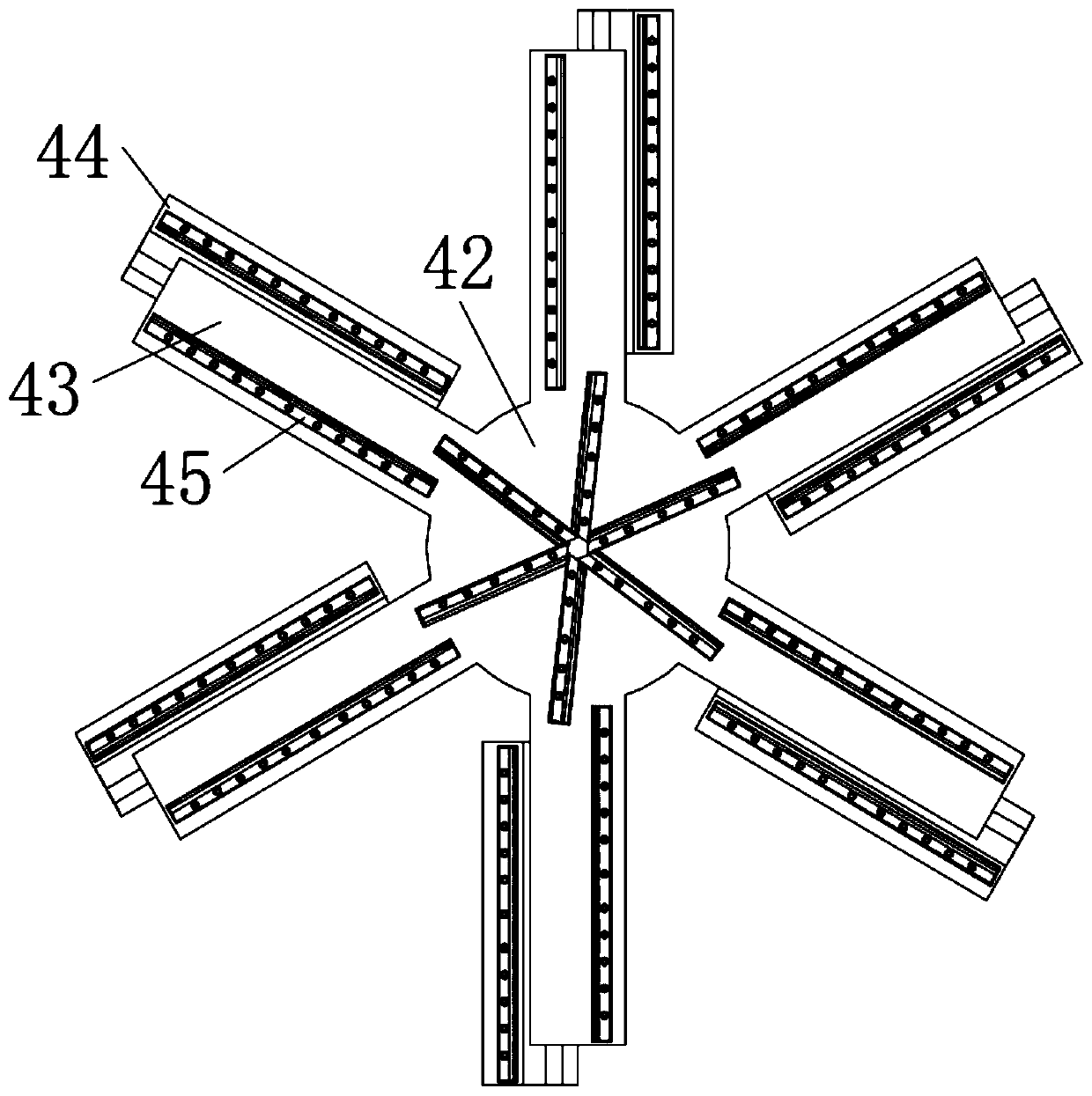
[0023] see Figure 1-8 , an embodiment provided by the present invention:

[0024] A drilling device with a protective structure for bridge construction, including a device casing 1, a drive motor 2, a water pump 61, a sludge pump 64 and an integrated switch 8, and a drive motor 2 is fixedly installed inside the device casing 1, the model of the drive motor 2 For the YE series, a transmission mechanism is installed under the device casing 1, and the transmiss...


PUM


Abstract

The invention discloses a working method of a punching device with a protective structure and for bridge construction. The punching device comprises a device shell, a driving motor, a water pump, a sludge pump and an integrated switch. The driving motor is fixedly installed inside the device shell. A transmission mechanism is installed on the lower portion of the device shell and comprises a rotating rod. The rotating rod is embedded into the middle of the bottom of the device shell through a bearing. A transmission sleeve is fixedly installed on the top of the rotating rod, and a transmissioninsertion block is arranged on the top of the transmission sleeve in an insertion mode. A connecting sleeve is fixedly installed at the bottom of the rotating rod, and a connecting insertion block isarranged at the bottom of the connecting sleeve in an insertion mode. A punching mechanism is installed at the bottom of the connecting insertion block. According to the punching device, due to the fact that polishing and cutting blades are arranged and installed at the bottom of the punching device, the hole forming operation can be conducted by the grinding operation, and the phenomenon that broken blocks generated by drilling splash and cause the harm to constructors is effectively avoided; and transverse fixing beams and transverse moving beams are arranged and can slide to be adjusted, and therefore the hole forming diameter of the device can be flexibly adjusted.

Description

technical field [0001] The invention relates to the technical field of bridge drilling equipment, in particular to a working method of a drilling device with a protective structure for bridge construction. Background technique [0002] With the movement of the trajectory of human life, in order to achieve rapid economic development, it has become a necessary requirement to open up both sides of the river. In today's technical means, bridges are usually built on the river to connect the two sides of the river, so that it is usually, but now Some bridges usually need to be drilled during the construction process to meet the operational requirements during construction. [0003] During the construction of existing bridges, drills, hole saws and other equipment are often used for drilling operations, which will produce hard impacts during use, causing powder and debris to splash everywhere, which is likely to cause injury to construction personnel; [0004] In addition, the dri...

Claims


Application Information

Patent Timeline
IPC IPC(8): B28D1/14B28D7/02
CPCB28D1/14B28D7/02
Inventor 寇俊祥高月民张小辉
Owner 安徽启源建筑工程有限公司
Learn More