A method for turning and milling compound processing of gyroscope wire guard

A process method and composite processing technology, applied in the field of mechanical processing, can solve the problems of reducing the processing accuracy and quality of parts, long auxiliary processing time for wire guard processing, and no published patent documents have been found, so as to reduce processing difficulty and shorten processing time. Auxiliary time, effect of shortening auxiliary processing time

Active Publication Date: 2021-05-07
TIANJIN NAVIGATION INSTR RES INST
View PDF8 Cites 0 Cited by
  • Summary
  • Abstract
  • Description
  • Claims
  • Application Information

AI Technical Summary

Problems solved by technology

[0015] It has been proved by the processing practice that although this process scheme can meet the processing requirements of the wire guard, due to the combination of turning and milling, the processing of the wire guard parts includes a large number of process clamping times, resulting in the processing of the wire guard. The auxiliary processing time is long, which seriously affects the processing efficiency; and the key structure of the part has high indexing accuracy requirements, and the multiple clamping of multiple types of work leads to the accumulation of clamping errors, which seriously reduces the processing accuracy and quality of the part. , there is a risk of out-of-tolerance accuracy, and at the same time increases the processing difficulty of the parts and reduces the processing efficiency of the parts
In addition, since the machining of the hole and arc groove of the part needs to be completed by the machining center, it is a typical example of single-person single-machine machining, and the machining process of the wire guard is multi-work processing, so that the machining process of the part Occupying a large amount of equipment resources in the turning and milling machining center, and consuming multiple types of labor such as turning and milling, which greatly increased the production cost of this part, resulting in the processing of wire guard parts becoming a key bottleneck in the supporting production of gyroscopes
[0016] Through the search of published patent documents, no published patent documents related to the application of the present invention were found

Method used


Image

  • A method for turning and milling compound processing of gyroscope wire guard
  • A method for turning and milling compound processing of gyroscope wire guard
  • A method for turning and milling compound processing of gyroscope wire guard

Examples


Embodiment Construction

[0043] The embodiments of the present invention will be described in further detail below in conjunction with the accompanying drawings; the present embodiments are descriptive, not restrictive, and cannot thereby limit the protection scope of the present invention.

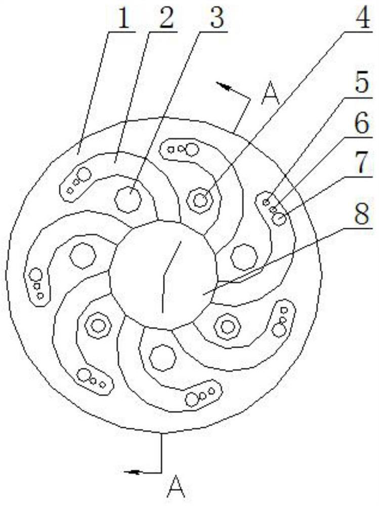
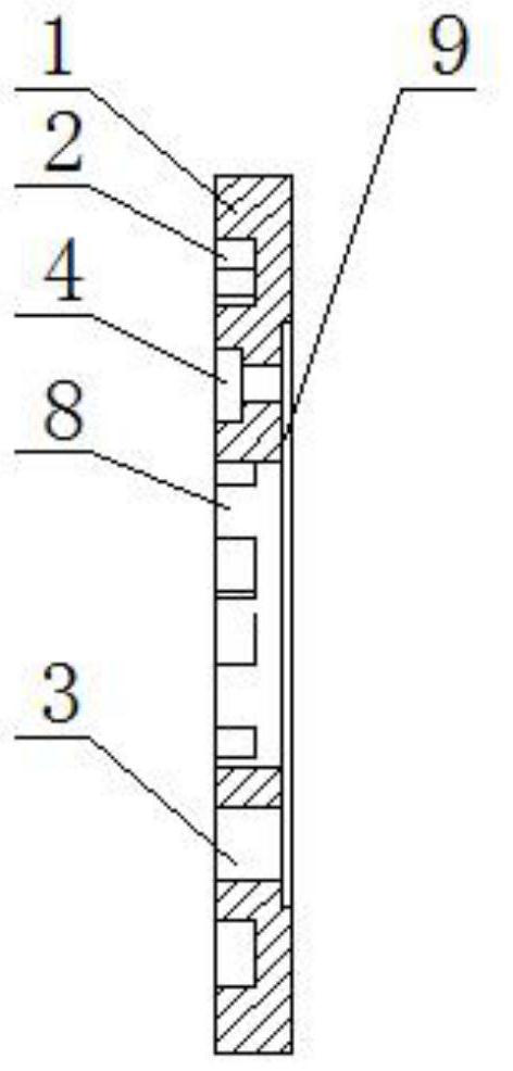
[0044] First describe the structure of the gyroscope wire guard of the present invention, see figure 2 , 3 , 4, 5, 6.

[0045] The gyroscope wire guard 1 is a disc-shaped structure, and its front structure is as follows: a central inner hole 8 is formed in the center of the disc. There are seven identical arc grooves 2, and the inner top of the arc groove is closed by an arc, and the bottom of the arc groove at the closed part of the arc is respectively made with φ0.8mm I through hole 5 and II through hole from inside to outside. The hole 6 and the through hole 7 of φ1.8mm are formed with three stepped holes 4 of φ3.5-φ1.8mm with the same diameter between the spaced arc grooves, and are formed between the rema...


PUM


Abstract

The invention relates to a turning-milling compound processing method for gyroscope wire guards. The steps are: (1) performing the first clamping on the lathe; (2) drilling concentric inner holes on the lathe; (3) milling a circle on the lathe. arc groove; ⑷drilling and countersinking on the lathe; ⑸finishing the concentric inner hole on the lathe; ⑹finishing the outer circle on the lathe; ⑺cutting off the workpiece on the lathe; ⑻turning over the lathe for the second assembly Clamp the workpiece; ⑼ Turn the back groove and finish turning end face on the lathe; ⑽ Measure, test, clean, pack and store. The invention creatively adopts the turning-milling composite processing technology in the processing technology of the gyroscope wire guard, the processing and survival of the workpiece can be completed only on the lathe, and the number of clamping times of the process is reduced from 5 times to 2 times, effectively reducing the number of times of workpiece loading. The number of clips can greatly shorten the auxiliary processing time, reduce the processing cost of parts, and improve the processing efficiency. It can meet the needs of small batch and large batch production of gyroscope wire guards, and can be extended to the production and processing of related thin sheet parts.

Description

technical field [0001] The invention belongs to the technical field of mechanical processing, and relates to the processing of gyroscope wire guards, in particular to a turning-milling composite processing method for gyroscope wire guards. Background technique [0002] The gyroscope wire guard is the key structural part of the gyroscope component, which belongs to the thin sheet part, and the structural features are mostly arc type, and the material is LY12-CZ aluminum alloy; the outer surface of the part has 7 uniformly distributed arc grooves, The end of each trunking is distributed with 3 through holes arranged in a specific order, with diameters of φ1.8mm, φ0.8mm and φ0.8mm respectively. In addition, there are 7 through holes designed in addition to the arc grooves on the outer surface of the wire guard parts. In order to ensure the shape and position accuracy of the wire guard structure, all the arc structures of this part have high indexing accuracy requirements, all ...

Claims


Application Information

Patent Timeline
Patent Type & Authority Patents(China)
IPC IPC(8): B23P13/02
CPCB23P13/02
Inventor 刘勇胡萌高建姚鑫陈明侯熙硕陈鹏刘媛媛
Owner TIANJIN NAVIGATION INSTR RES INST
Why Eureka
Try Eureka