
Integrated sightseeing lift with steel-structured hoistway

A sightseeing elevator and steel structure technology, which is applied in the field of mechanical lifting, can solve the problems that the installation of elevators cannot be realized, the total cost of installing elevators increases, and the construction period is long.

Active Publication Date: 2014-03-26
福建快科城建增设电梯股份有限公司
View PDF5 Cites 5 Cited by
  • Summary
  • Abstract
  • Description
  • Claims
  • Application Information

AI Technical Summary

Problems solved by technology

Although this kind of steel structure hoistway saves the trouble of welding, there are many steel components and the structure is relatively complicated, which requires high assembly of steel components. The installation quality, operation reliability and riding comfort of the elevator in the well, so the construction period is still very long, and the installation cost is also high
In addition, the construction of the existing steel structure shaft is completely separated from the installation of the elevator. Usually, the elevator is installed and debugged after the construction of the shaft. Therefore, the total time for the installation of the outdoor elevator is very long, and the labor costs on site are also large, resulting in The total cost of installing elevators increases, and the installation of elevators in many multi-storey buildings will not be realized because of this.

Method used


Image

  • Integrated sightseeing lift with steel-structured hoistway
  • Integrated sightseeing lift with steel-structured hoistway
  • Integrated sightseeing lift with steel-structured hoistway

Examples


Embodiment Construction

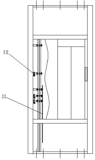
[0022] refer to Figure 1~2 , a sightseeing elevator with a steel structure hoistway integrated, comprising a car 4 and a counterweight device 15, characterized in that it also includes a base 12, a bottom frame 16, a plurality of intermediate frames 18, and a top frame from bottom to top 21 and top cover 24, the base 12, the bottom frame 16, a plurality of intermediate frames 18, the top frame 21 and the top cover 24 are stacked and installed to form a steel structure hoistway, and the car is installed in the top frame 21. 4. The traction system for lifting and lowering in the steel structure hoistway. The bottom frame 16, the multiple intermediate frames 18 and the top frame 21 are respectively installed with guides that enable the car 4 and the counterweight device 15 to move up and down along the guide rails. system and the door system that seals the entrance of the landing; above the four columns of the bottom frame 16, a plurality of intermediate frames 18 and the top fr...


PUM


Abstract

The invention relates to an integrated sightseeing lift with a steel-structured hoistway. The integrated sightseeing lift comprises a car and a counterweight device and is characterized by comprising a base, an underlayer framework, a plurality of intermediate-layer frameworks, a top-layer framework and a top cover from the bottom up in sequence, wherein the base, the underlayer framework, the plurality of intermediate-layer frameworks, the top-layer framework and the top cover are overlapped and installed to form the steel-structured hoistway; the top-layer framework is internally provided with a traction system for lifting the car in the steel-structured hoistway, the underlayer framework, the plurality of intermediate-layer framework and the top-layer framework are internally and respectively provided with a guide system and a door system, the guide systems are used for enabling the car and the counterweight device to be lifted only along a guide rail, and the door systems are used for sealing the entrance of each floor. The invention further provides a corresponding modularized installation method for the integrated sightseeing lift with the steel-structured hoistway. The integrated sightseeing lift with the steel-structured hoistway has the advantages of compact structure, safety, reliability and attractive, novel appearance and the like, and is suitable for being installed in multi-floor constructed buildings, and the modularized installation method for the integrated sightseeing lift has the advantages of short construction period and low cost.

Description

technical field [0001] The invention relates to a sightseeing elevator with an integrated steel structure shaft, which is particularly suitable for installing a sightseeing elevator with an integrated steel structure shaft outside an existing multi-storey building, and belongs to the technical field of mechanical lifting. Background technique [0002] With the acceleration of population aging process and the improvement of residents' living standards, the demand for installing elevators in multi-storey buildings will also increase day by day. The multi-storey building has been built to install elevators because there is no well design in advance. The usual way is to add an outdoor shaft for elevator installation and operation. However, the existing steel structure wells are formed by integral on-site welding or on-site tailor-welding of prefabricated steel components, which requires high-altitude welding technology. The entire construction process is carried out outdoors, wh...

Claims


Application Information

Patent Timeline
Patent Type & Authority Patents(China)
IPC IPC(8): B66B9/00B66B11/04B66B7/00
Inventor 张凡陈敏
Owner 福建快科城建增设电梯股份有限公司
Learn More