Ground mat production method
A production method and technology for floor mats, which are applied to carpets, sound-producing devices, instruments, etc., can solve problems such as poor sound insulation effect, and achieve the effects of good sound insulation effect, high use value and less cost increase.
- Summary
- Abstract
- Description
- Claims
- Application Information
AI Technical Summary
Problems solved by technology
Method used
Image


Examples
Embodiment 1
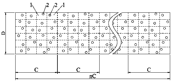
[0045] This embodiment provides a floor mat, such as figure 1 As shown, the floor mat includes a floor mat body made of foam material, and at least one surface of the floor mat body is formed with several sound-insulating units 1 with the same area. The sound-insulating unit 1 has at least one sound-insulating structure 2. The sound insulation structures 2 inside are different in at least one of quantity, shape and distribution position.
[0046] When the sound passes through the surface of the sound insulation structure 2 which is irregularly distributed, the air in the sound insulation structure 2 is caused to vibrate. Due to the frictional resistance, the viscous resistance of the air and the heat conduction, a considerable part of the sound energy is converted into heat energy, thus playing a role. Sound absorption; at the same time, since the sound is usually transmitted in a straight direction, when the sound insulation structure 2 is irregularly distributed, part of the...
Embodiment 2
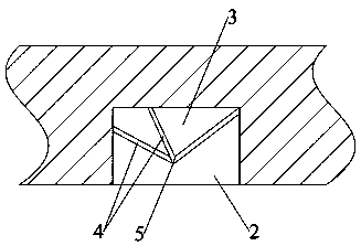
[0070] like image 3 As shown, the difference between this embodiment and Embodiment 1 is that the sound insulation structure 2 in this embodiment is not provided with blind holes, but a scattering block 3 with multiple scattering surfaces protruding directly to the side of the floor mat body , several scattering surfaces of each scattering block 3 form a blocking part 4 at the intersection, and among all the blocking parts 4 of each scattering block 3, the blocking part 4 farthest from the center layer of the floor mat forms a support for interacting with the ground Part 5, the distance between the supporting parts 5 of two adjacent scattering blocks 3 and the center layer of the floor mat is equal. When the sound touches the scattering surface and the blocking part 4, it is anisotropically reflected by the irregular surface, dispersed to form a plurality of chaotic sounds which cancel each other out, effectively isolating most of the sounds. The support part 5 is used for s...
Embodiment 3
[0073] This embodiment is an explanation for the sound insulation structures 2 in adjacent sound insulation units 1 described in the first embodiment having at least one difference in number, shape and distribution position. In the floor mat provided in this embodiment, the number and shape of the sound insulation structures 2 in adjacent sound insulation units 1 are the same, but the distribution positions are different. The following is an example of the structure of the floor mat of this embodiment.
[0074] Example 1: If Figure 4 As shown, the number of sound insulation structures 2 in adjacent sound insulation units 1 is one and all are blind holes, and the distribution positions of the blind holes in adjacent sound insulation units 1 are different in the corresponding sound insulation units 1 . Figure 4 Among the four sound insulation units 1 distributed in the middle array, the blind hole in the first sound insulation unit 1 is located at the center of the sound insu...
PUM
 Abstract
Description
Claims
Application Information
 - R&D
- Intellectual Property
- Life Sciences
- Materials
- Tech Scout
- Unparalleled Data Quality
- Higher Quality Content
- 60% Fewer Hallucinations
Browse by: Latest US Patents, China's latest patents, Technical Efficacy Thesaurus, Application Domain, Technology Topic, Popular Technical Reports.
© 2025 PatSnap. All rights reserved.Legal|Privacy policy|Modern Slavery Act Transparency Statement|Sitemap|About US| Contact US: help@patsnap.com