High-salt wastewater treatment method
A waste water treatment, high salt content technology, applied in the direction of heating water/sewage treatment, etc., can solve the problems of large floor space and operating costs, high requirements and price comparison, waste of investment, etc., to increase air moisture absorption capacity and increase temperature , Improve the effect of evaporation capacity
- Summary
- Abstract
- Description
- Claims
- Application Information
AI Technical Summary
Problems solved by technology
Method used
Image

Examples
Embodiment
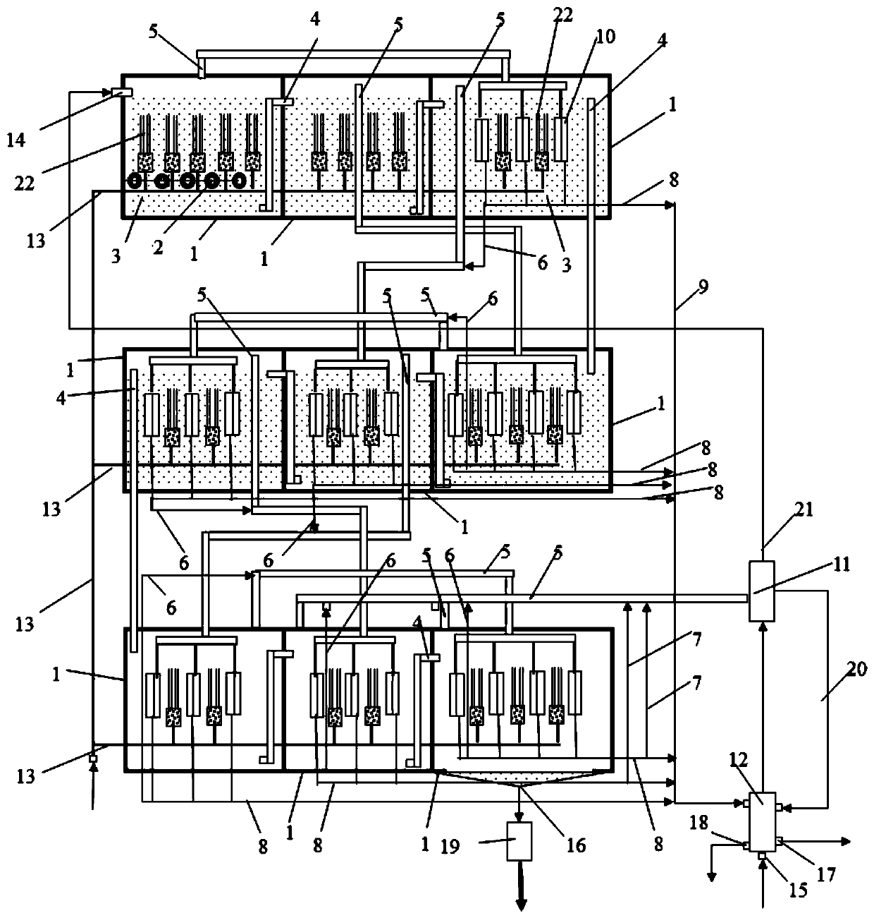
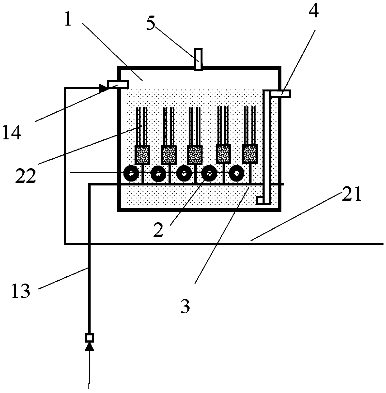
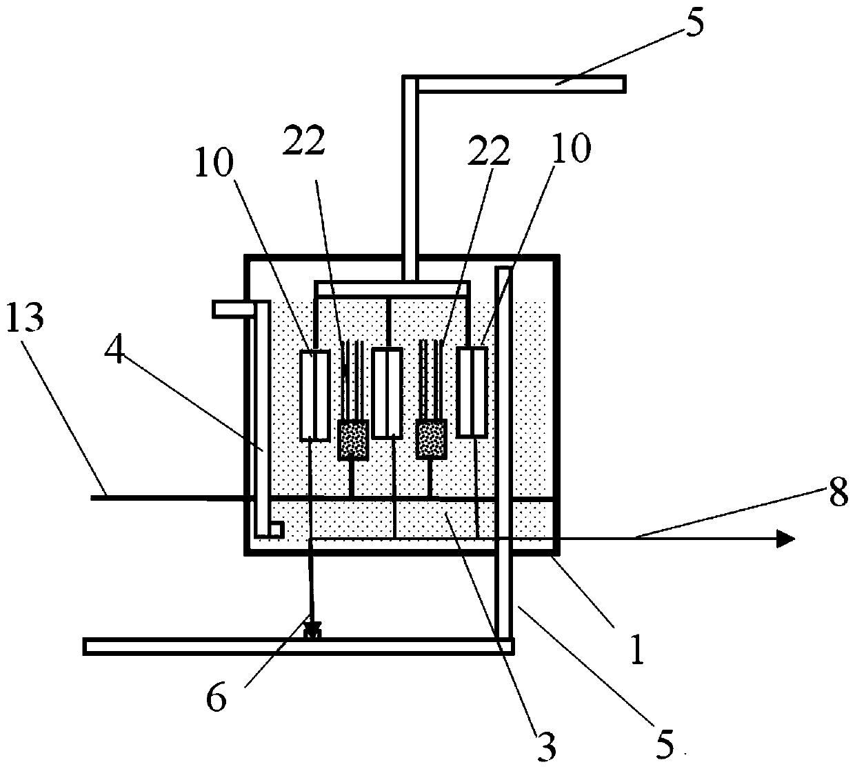
[0029] like Figure 1~4 As shown, this embodiment discloses a high-salt wastewater treatment method that forms nine stages of evaporation when n=9. This embodiment includes nine evaporation tanks 1, overflow pipes 4, raw material liquid pipes 21, and heaters 2 , Water collection pipe 8, water production pipe 9, main air collection pipe 5, first auxiliary air collection pipe 6, first outlet 16, second feed port 14, third heat exchanger 10. Specifically, the system consists of nine evaporation tanks connected in series to form a nine-stage evaporation system. The nine evaporation tanks can be connected in series from top to bottom, and from top to bottom are the first-stage evaporation tank, the second-stage evaporation tank and The third-stage evaporation tank is connected in series on the first floor, the fourth-stage evaporation tank, the fifth-stage evaporation tank and the sixth-stage evaporation tank are connected in series on the second floor, the seventh-stage evaporatio...
example 1
[0049] For the treatment of fracturing flowback fluid at a well site in Ordos, Inner Mongolia, there are 9 evaporation water tanks in the evaporation concentration system used at this time, forming a 9-stage evaporation concentration system. First, the raw material liquid is obtained by removing fine particles such as suspended solids in the raw material liquid through flocculation and sedimentation treatment of the flowback liquid, and the raw material liquid is pumped into the first-stage evaporation water tank in the 9-stage evaporation concentration system through the raw material liquid, and the heating temperature is set After the temperature gradient at each level is formed (the first level is 90°C, followed by 85°C, 80°C, 75°C, 70°C, 65°C, 60°C, 55°C, 50°C), the membrane aeration fan is turned on and passes through the trachea to the Air is introduced into the aeration membrane module for evaporation treatment. During the evaporation process, the condensed water produce...
example 2
[0051]For the fracturing flowback fluid treatment of a shale gas drilling platform in Dazu, Chongqing, there are 6 evaporation water tanks in the evaporation concentration system used at this time, forming a 6-stage evaporation concentration system. First, the suspended matter in the raw material liquid is removed by flocculation and sedimentation of the flowback liquid, and the raw material liquid is pumped into the first-stage evaporation water tank in the 6-stage evaporation concentration system through the raw material liquid, and the heating temperature is set, and the temperature gradient of each level is After formation (the first stage is 90°C, followed by 85°C, 80°C, 75°C, 70°C, 65°C) the membrane aeration fan is turned on and the air is passed into the aeration membrane module through the air pipe for evaporation treatment. The condensed water produced by the phase change in the heat exchanger during the evaporation process is discharged into the water production tank...
PUM
 Abstract
Description
Claims
Application Information
 - R&D
- Intellectual Property
- Life Sciences
- Materials
- Tech Scout
- Unparalleled Data Quality
- Higher Quality Content
- 60% Fewer Hallucinations
Browse by: Latest US Patents, China's latest patents, Technical Efficacy Thesaurus, Application Domain, Technology Topic, Popular Technical Reports.
© 2025 PatSnap. All rights reserved.Legal|Privacy policy|Modern Slavery Act Transparency Statement|Sitemap|About US| Contact US: help@patsnap.com