A molding die for a hinge connecting part of a display bracket

A display bracket and shaft connection technology, which is applied in the field of forming molds for shaft joints, can solve problems that restrict the development and promotion of integrated shaft connections, increase labor costs, equipment supporting costs, and high production costs, etc., to achieve reduction The effect of labor cost, ensuring positioning, and stable installation

Active Publication Date: 2021-03-19
厦门山润峰工贸有限公司
View PDF9 Cites 0 Cited by
  • Summary
  • Abstract
  • Description
  • Claims
  • Application Information

AI Technical Summary

Problems solved by technology

[0006] like figure 1 As shown, the prior art is similar to the above-mentioned hinge connector 1 for the display stand, which generally includes a body 11 (ie, the longitudinal rotating body in the prior art 1 or the connector in the prior art 2) and a The connecting shaft 12 on the left and right ends of the body (i.e. the second rotating shaft in the prior art 1 or the pivot in the prior art 2), when in use, by installing a connecting piece on the connecting shaft (i.e. the second rotating shaft in the prior art 1 The horizontal rotating body or the bracket in prior art 2) can be used; wherein, according to the above two prior art, the existing connecting shaft has integral molding (that is, between the second rotating shaft and the longitudinal rotating body in prior art 1). The connection method) and the plug-in type (that is, the connection method between the pivot and the connector in the prior art 2), the production cost of the plug-in type is relatively low, but because the pivot is fixed only by a nut, Therefore, once the nut (that is, the fastener in the prior art 2) that is threadedly connected with the pivot used as the connecting shaft becomes loose, the entire display screen will collapse immediately, so there is a certain potential safety hazard; and the integrated production cost Although it is relatively high, because the two integrated second rotating shafts are respectively fixed by two nuts (that is, the locking piece in prior art 1), even if one of the nuts is loose, the display screen can still be connected to a certain Even if the display is forced to rotate due to the heavy weight of the connection, the rotation angle of the connection will be greatly reduced, preventing the display from collapsing directly, so it is safer to use
[0007] Among them, there are two main production methods for the integrated shaft connector, one is to cast the body directly, and then weld the threaded connecting shaft on both ends of the body, and the other is to cast the body and the connecting shaft integrally Forming, and then forming threads on the connecting shaft, no matter what method is used, the production steps of the existing one-piece rotating shaft connection with higher safety need two steps to complete, and adding a process represents labor costs and equipment matching. The increase of cost and the reduction of production efficiency, therefore, the production cost of the existing one-piece shaft connection has been high, which seriously restricts the development and promotion of the one-piece shaft connection with higher safety

Method used


Image

  • A molding die for a hinge connecting part of a display bracket
  • A molding die for a hinge connecting part of a display bracket
  • A molding die for a hinge connecting part of a display bracket

Examples


Embodiment 1

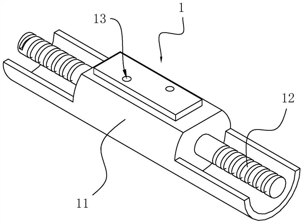
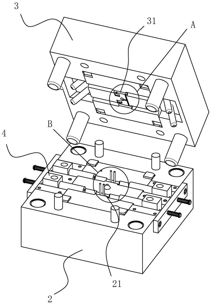
[0047] Embodiment 1: A forming mold for the hinge connecting piece of the display bracket, combined with figure 2 with image 3 As shown, it includes a left mold 2 and a right mold 3 and several sets of connecting shaft positioning components 4 arranged on the left mold 2 and arranged along the height direction of the left mold 2 for realizing the integral molding of the connecting shaft 12 and the body 11; On the side of the left mold 2 facing the right mold 3, there are several first grooves 21 arranged along the height direction of the left mold 2; The second grooves 31 arranged in the height direction, when the left mold 2 and the right mold 3 are merged, each first groove 21 cooperates with each second groove 31 to enclose and form several grooves for forming the body 11 cavity.

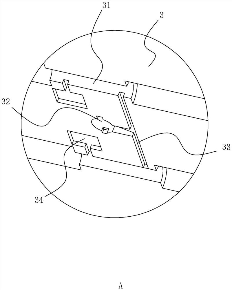
[0048] which, combined with image 3 As shown, the right mold 3 is provided with a runner 32 for injection of the molten metal solution into the molding die, and a runner 33 communicating wi...

Embodiment 2

[0059] Embodiment two: if Figure 11 As shown, the difference from Embodiment 1 is that each positioning member 41 is provided with an inclined guide surface 412, and the two ends of each inclined guide surface 412 are respectively connected to the side of the positioning member 41 away from the first groove 21. And the locating piece 41 is connected away from the side of the left mold 2, and the right mold 3 is provided with several wedge-shaped pieces 38 that are respectively matched with each piece of locating piece 41 in quantity and position. When the left mold 2 and the right mold 3 merged, each The wedge blocks 38 respectively abut against the inclined guide surfaces 412 for pushing the positioning member 41 to move toward the direction where the first groove 21 is located.

[0060] When the left mold 2 and the right mold 3 are separated, each piece of wedge block 38 will move away from the left mold 2. At this time, each piece of second elastic member 52 resets, thereb...


PUM


Abstract

The invention discloses a forming mold used for a rotating shaft connecting part of a display screen support, and relates to the technical field of display support production equipment, and solves thetechnical problem that the integrated rotating shaft connecting part needs two processes to form. The main technical points of the forming mold is that the forming mold comprises a left mold and a right mold, a first forming groove is arranged in the left mold, a second forming groove is arranged in the right mold, the forming mold further comprises s connecting shaft positioning component whichis arranged in the left mold, the connecting shaft positioning component comprises two positioning parts which are slidably connected on one face, which faces the right mold, on the left mold and arerespectively located on the left and right ends of the first forming groove, an inserting groove which is used for connecting a connecting shaft in an inserting manner is arranged on faces, which arearranged relatively, of the two positioning parts, the sliding direction of the two positioning parts is arranged along the axis direction of the inserting groove, the right mold is provided with a plurality of avoiding grooves which are used for the movement of the positioning parts of each part, and the connecting shaft which are connected in the inserting groove in an inserted manner is locatedin a first forming cavity. The forming mold used for the rotating shaft connecting part of the display screen support has the advantage of one-time forming of the integrated rotating shaft connectingpart.

Description

technical field [0001] The invention relates to the technical field of production equipment for display screen brackets, and more specifically, it relates to a molding die for a rotating shaft connector of a display screen bracket. Background technique [0002] A display is also commonly referred to as a monitor. A monitor is an I / O device belonging to a computer, that is, an input and output device. It is a display tool that displays certain electronic files on the screen through a specific transmission device and then reflects them to the human eye. According to different manufacturing materials, the existing display screen can be divided into: cathode ray tube display (CRT), plasma display PDP, liquid crystal display LCD and so on. [0003] In order to facilitate the use of users, the existing display screens are generally equipped with adjustable brackets. The brackets mainly play two roles. It is safe to use, and the other is to adjust the activity, mainly to enable t...

Claims


Application Information

Patent Timeline
Patent Type & Authority Patents(China)
IPC IPC(8): B22D17/22
CPCB22D17/22
Inventor 余华明余华喜
Owner 厦门山润峰工贸有限公司
Why Eureka
Try Eureka