
An Intelligent Network Fault Finding and Calibration Device

A technology for calibrating device and network failure, applied in the direction of failure location, measuring device casing, etc., can solve problems such as tipping collision, damage to electronic components, etc., and achieve the effect of simple structure and damage prevention.

Active Publication Date: 2021-11-16
慧普系统集成科技(江苏)有限公司
View PDF14 Cites 0 Cited by
  • Summary
  • Abstract
  • Description
  • Claims
  • Application Information

AI Technical Summary

Problems solved by technology

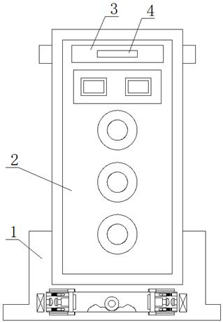
[0004] The purpose of the present invention is to solve the problem that many electronic components are often integrated in the network fault finding device in the prior art. When moving the position, it needs to be transported, but dumping and collisions often occur during the transporting process. , which in turn will cause damage to the internal electronic components, and an intelligent network fault finding and calibration device is proposed

Method used


Image

  • An Intelligent Network Fault Finding and Calibration Device
  • An Intelligent Network Fault Finding and Calibration Device
  • An Intelligent Network Fault Finding and Calibration Device

Examples


Embodiment 1

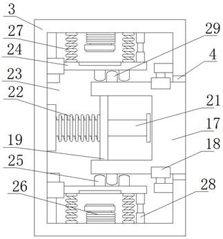
[0026] refer to Figure 1-5 , an intelligent network fault finding and calibration device, comprising a support base 1, a network fault finding and calibration device body 2 is fixedly installed on the top of the support base 1, and anti-collision seats 3 are fixedly installed on the four sides of the network fault finding and calibration device body 2 There is an installation cavity 5 on the support base 1, a positioning block 6 is fixedly installed on the middle position of the installation cavity 5, a rolling ball 7 is placed on the middle position of the top of the positioning block 6, and two symmetrically arranged sliding balls are connected in the installation cavity 5. two moving plates 8, and the two moving plates 8 are respectively located on both sides of the positioning block 6, the first conductive sheets 9 are fixedly installed on both sides of the two moving plates 8, and the inner walls on both sides of the installation cavity 5 are fixedly installed with The s...

Embodiment 2

[0028]Further improvement on the basis of Embodiment 1: a sliding hole 20 is opened on the mounting plate 19, and the guide rod 21 passes through the sliding hole 20 and is slidably connected with the sliding hole 20. When moving, limit the position so that it will not shift when it moves; the elastic component includes two symmetrically arranged sliding blocks 11 fixedly installed on the inner walls of both sides of the installation cavity 5 respectively, and one side of the sliding block 11 is fixedly installed with a sliding block. Two sliding seats 13 arranged symmetrically are fixedly installed on the sides of the rod 12 and the two moving plates 8 away from each other. One side of the sliding seats 13 is provided with a sliding groove 14, and the sliding rod 12 extends into the corresponding sliding groove 14. And slidingly connected with the slide groove 14, the outer side of the slide bar 12 is provided with a support spring 15, one end of the support spring 15 is fixed...


PUM


Abstract

The invention belongs to the technical field of electric power dispatching automation system, in particular to an intelligent network fault finding and calibration device, aiming at that when the existing network fault finding device moves its position, there will often be dumping and collision during the transportation process, which will further cause internal damage. The problem of damage to electronic components is now proposed as follows, which includes a support base. The top of the support base is fixedly equipped with a network fault finding and calibration device body. There is an installation cavity on the support seat; when the main body of the transport network fault finding and calibration device is dumped, the rolling ball will roll, and once the rolling ball hits the moving plate, the anti-collision block will pop out from the fixed cavity, and then The protection of the overturned network fault finding and calibration device body is realized, and the electronic components inside the network fault finding and calibration device body are effectively prevented from being damaged.

Description

technical field [0001] The invention relates to the technical field of power dispatching automation systems, in particular to an intelligent network fault finding and calibration device. Background technique [0002] In the power dispatching automation system, when a device or external line in the network fails, it is necessary to find the fault through the manual label on the device or the network cable, and it is impossible to quickly and accurately locate the faulty device, find the fault and then eliminate the fault during the search process caused great difficulties. The Chinese patent with the notification number CN109005074A discloses a network connection two-dimensional code generation method, a network fault finding method and device, which belong to the two-dimensional code technical field. The network connection two-dimensional code generation method provided by the embodiment of the present invention generates a two-dimensional code database according to the dev...

Claims


Application Information

Patent Timeline
Patent Type & Authority Patents(China)
IPC IPC(8): G01R1/04G01R31/08
CPCG01R1/04G01R31/08
Inventor 初海波
Owner 慧普系统集成科技(江苏)有限公司
Learn More