Foldable multifunctional walking aid
A walking aid and multi-functional technology, which is applied in the direction of walking aids, physical therapy, etc., can solve the problems of overall bulkiness, inability to fold, inability to change the way of use, etc.
- Summary
- Abstract
- Description
- Claims
- Application Information
AI Technical Summary
Problems solved by technology
Method used
Image
Examples
Embodiment 1
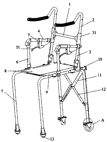
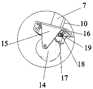
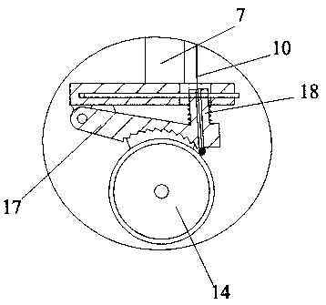
[0060] as attached figure 1 to attach Image 6 As shown, the foldable multifunctional walker includes an upper connecting rod 1 and a lower connecting rod. The upper connecting rod 1 is symmetrically provided with an upper frame assembly on both sides perpendicular to the advancing direction of the walker, and the lower connecting rod is perpendicular to the walking aid. The lower frame components are arranged symmetrically on both sides of the forward direction of the machine;
[0061]The lower frame assembly includes the lower bracket 7 with the opening facing downwards in a U-shaped structure. The lower brackets 7 on both sides are connected to the front side of the walker through the lower connecting rod. The lower connecting rod can make the lower brackets 7 on both sides Close to or far away from each other, the two ends of the U-shaped opening of the lower bracket 7 are provided with rolling wheels, and the upper end of the U-shaped structure of the lower bracket 7 is ...
Embodiment 2
[0083] The difference between embodiment two and embodiment one is:
[0084] as attached Figure 8 to attach Figure 10As shown, in this embodiment, the end of the left seat 9 away from its connection with the lower bracket 7 protrudes along the advancing direction of the walker to be provided with a plurality of first connecting bars 95, and the left seat 9 protrudes along the advancing direction of the walker. One end of the left seat 9 is flush with the end face of the first connecting bar 95 at the corresponding position, and the other end of the left seat 9 protrudes from the end face of the first connecting bar 95 at the corresponding position along the forward direction of the walker. The vertical direction of the first connecting bar 95 is The two end faces are flush with the two end faces in the vertical direction of the left seat 9, and the lower end face of the first connecting bar 95 is provided with a plurality of inverted trapezoidal structures running through t...
Embodiment 3
[0087] The difference between embodiment three and embodiment one is:
[0088] as attached Figure 11 to attach Figure 12 As shown, in the present embodiment, the left seat 9 includes a left connecting block, a left connecting rod 97 and a left seat plate, the left connecting block is rotatably connected to the lower bracket 7 on the corresponding side, and the left connecting block is away from the lower bracket 7 connected to it. One side of one side is fixedly connected with the left seat plate and the left connecting rod 97, and the left connecting rod 97 stretches out the left seat plate away from the side where it connects the left connecting block, and is provided with a left thread at the part stretching out the left seat plate;
[0089] The right seat 8 comprises a right connecting block, a right connecting rod 86 and a right seat plate, the right connecting block is rotatably connected to the lower support 7 on the corresponding side, and the right connecting block...
PUM
 Abstract
Description
Claims
Application Information
 - R&D
- Intellectual Property
- Life Sciences
- Materials
- Tech Scout
- Unparalleled Data Quality
- Higher Quality Content
- 60% Fewer Hallucinations
Browse by: Latest US Patents, China's latest patents, Technical Efficacy Thesaurus, Application Domain, Technology Topic, Popular Technical Reports.
© 2025 PatSnap. All rights reserved.Legal|Privacy policy|Modern Slavery Act Transparency Statement|Sitemap|About US| Contact US: help@patsnap.com


