
An automatic slot milling device applied to the production of smart cards and its application method

A slot milling device and smart card technology, which is applied in the direction of feeding device, positioning device, milling machine equipment, etc., can solve the problems of lower production efficiency, time-consuming and labor-intensive, inconvenient smart card slot milling operations, etc.

Active Publication Date: 2022-02-11
靖州鑫兴智能科技有限公司
View PDF6 Cites 0 Cited by
  • Summary
  • Abstract
  • Description
  • Claims
  • Application Information

AI Technical Summary

Problems solved by technology

[0003] In the process of producing smart cards, it is necessary to mill grooves at specified positions on the smart cards so as to package chips in the milled grooves, but the existing milling groove devices have the following defects: 1. The smart cards are directly placed on the On the conveyor belt, it is not convenient for the milling cutter to mill the smart card; 2. When the smart card is conveyed to the bottom of the milling cutter, the smart card needs to be clamped by the clamping device again before the milling operation, which not only adds a process, but also Increase the workload of workers; 3. After the smart card slot milling is completed, the smart card needs to be collected, and a large number of workers are required to collect it, which is not only time-consuming and labor-intensive, but also inefficient and reduces production efficiency. Therefore, we propose An automatic slot milling device applied to the production of smart cards and its use method to solve the above-mentioned problems

Method used


Image

  • An automatic slot milling device applied to the production of smart cards and its application method
  • An automatic slot milling device applied to the production of smart cards and its application method
  • An automatic slot milling device applied to the production of smart cards and its application method

Examples


Embodiment 1

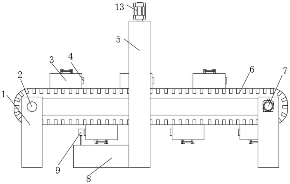
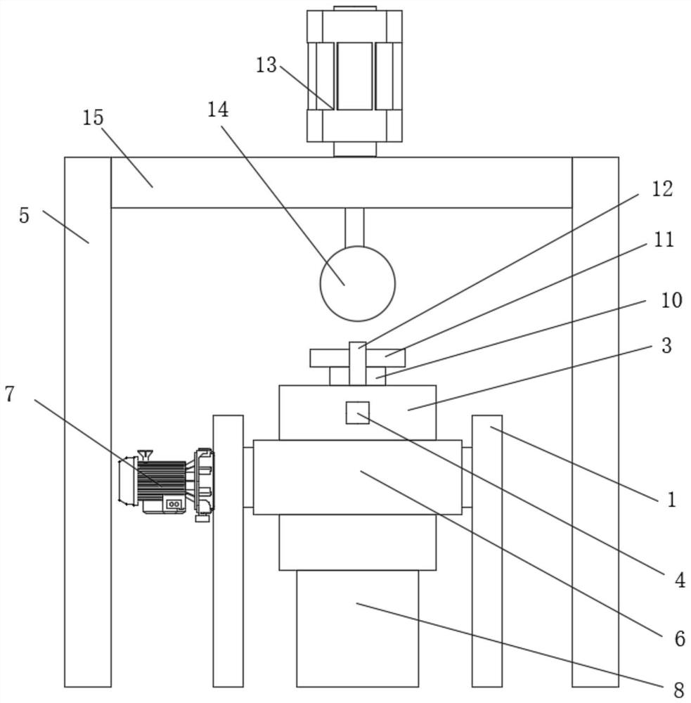
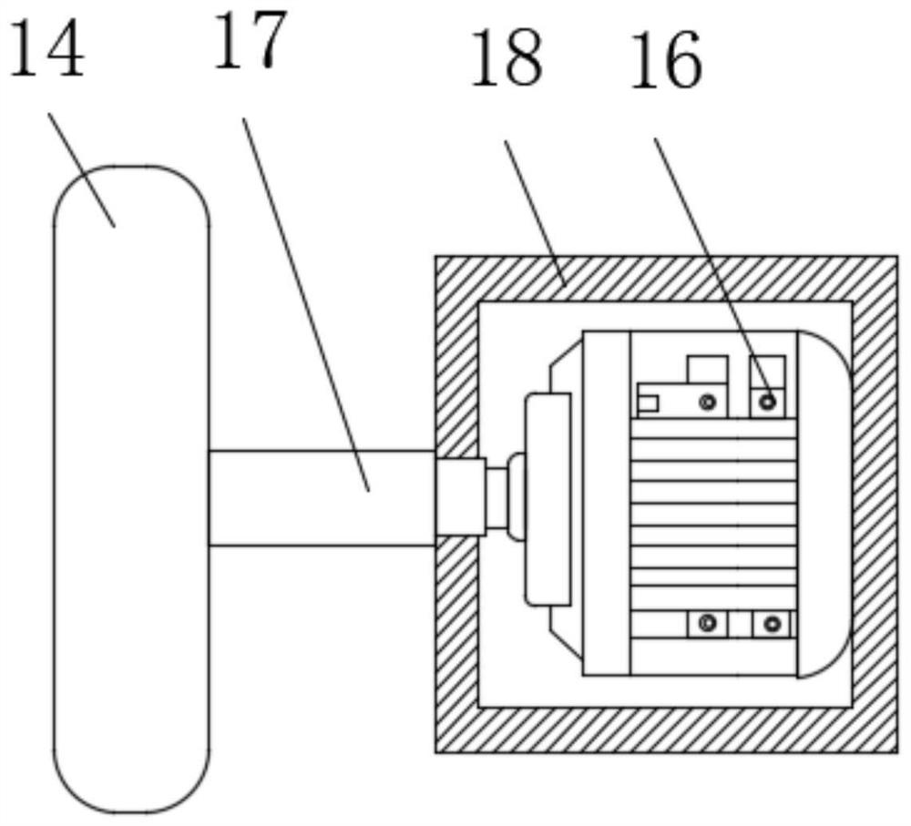
[0039] Embodiment one: if Figure 1-8 As shown, an automatic slot milling device applied to the production of smart cards includes a smart card body 11 and four fixed columns 1 that are symmetrical in pairs. Roller 2, the outer walls of the two rotating rollers 2 are covered with the same conveyor belt 6, the outer wall of the conveyor belt 6 is fixedly connected with a plurality of storage boxes 3, and one side of one fixed column 1 is fixedly connected with the first motor 7, the first motor The output shaft of 7 runs through the fixed column 1 and is fixedly connected with the rotating roller 2. The fixing assembly for fixing the smart card body 11 is arranged inside the storage box 3, and side plates 5 are arranged on both sides of the conveyor belt 6, and the two side plates 5 are connected to each other. The top of the adjacent side is fixedly connected with the same top plate 15, and the bottom of the top plate 15 is fixedly connected with a milling assembly for milling...


PUM


Abstract

The invention discloses an automatic slot milling device applied to the production of smart cards, which comprises a smart card body and four pairwise symmetrical fixing columns, and the sides of the two fixing columns located on the same side are close to each other are rotatably connected with the same rotating The outer wall of the two rotating rollers is covered with the same conveyor belt, the outer wall of the conveyor belt is fixedly connected with a plurality of placement boxes, one side of one of the fixed columns is fixedly connected with a first motor, and the first The output shaft of the motor runs through the fixed column and is fixedly connected with the rotating roller, which also discloses a use method. The beneficial effects of the present invention are: the present invention has a simple structure, and the smart card body is fixed through the fixing assembly. When the fixed smart card body moves to the bottom of the milling cutter, the first motor is turned off to start the milling process. Start the first motor, and release the brake on the smart card body through the contact and extrusion of the baffle and the button, so as to realize the collection process, and the operation is simple.

Description

technical field [0001] The invention relates to the field of smart card production, in particular to an automatic slot milling device applied to the production of smart cards and a use method thereof. Background technique [0002] A smart card is a general term for a plastic card that has a microchip embedded in it. Some smart cards contain a microelectronic chip, and smart cards need to exchange data through a reader. The smart card is equipped with CPU, RAM and I / O, and can process a large amount of data by itself without interfering with the work of the host CPU. Smart cards can also filter erroneous data to reduce the burden on the host CPU. It is suitable for occasions where the number of ports is large and the communication speed is required to be fast. The integrated circuit in the card includes a central processing unit CPU, a programmable read-only memory EEPROM, a random access memory RAM and a card operating system COS solidified in the read-only memory ROM. T...

Claims


Application Information

Patent Timeline
Patent Type & Authority Patents(China)
IPC IPC(8): B23C3/28B23Q3/06B23Q7/00B23Q5/28
CPCB23C3/28B23Q3/06B23Q7/00B23Q5/28B23Q3/062
Inventor 李子豪
Owner 靖州鑫兴智能科技有限公司
Learn More